EMAIL SUPPORT
dclessons@dclessons.comLOCATION
USVPC and L3 Design Scenarios
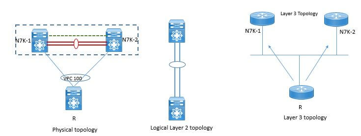
Whenever any layer 3 is connected to vPC domain through vPC, each vPC peer device is seen as distinct L3 device by rest of the network.
Below figure shows the distinct views depending on layer 2 and Layer 3 version on network.
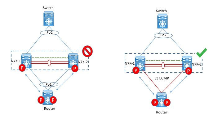
Connecting any L3 device to vPC domain using vPC is not supported because of vPC loop avoidance rule. If you want to connect any Layer 3 device to vPC domain than use L3 links from l3 device to each vPC peer device where these link can be one and to up to 16 and thus provides ECMP function and load balances the traffic across all L3 links.
L3 device will not initiate the L3 routing protocol adjacencies with both vPC peer devices. Traffic from L3 device to vPC domain (i.e. vPC peer device 1 and vPC peer device 2) can be load-balanced across all the L3 links interconnecting the 2 entities together.
There is then no penalty to use L3 links to connect L3 device to vPC domain compared to a vPC connection (in the sense that multiple links can also be leveraged with L3 connectivity)
vPC & L3 connectivity Designs
Following are some supported topology and shows how we should connect the Layer 3 device to vPC domain.
Strong Recommendations:
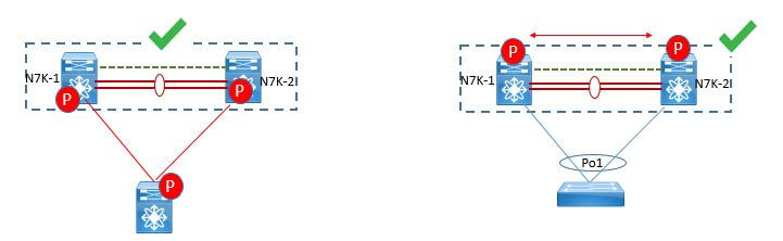
- Use separate Layer 3 links to connect L3 device (like router or firewall in routed mode for instance) to a vPC domain (Figure 50).
- Do not use a Layer 2 vPC to attach L3 device to a vPC domain unless L3 device can statically route to the HSRP address configured on vPC peer devices.
- Use individual Layer 3 links for routed traffic and a separate Layer 2 port-channel for bridged traffic if both routed and bridged traffic are required.
- Enable Layer 3 connectivity between vPC peer device by configuring a VLAN network interface for the same VLAN from both devices or by using a dedicated L3 link between the 2 peer devices (for L3 backup routing path purposes).
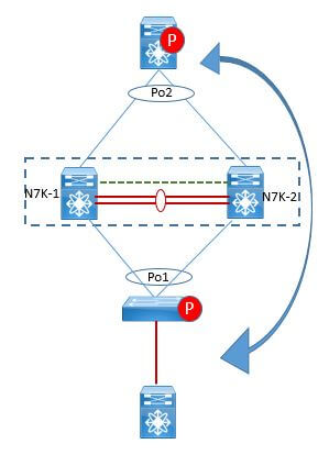
In this design, vPC is used as a pure L2 transit path. Because there is no direct routing protocol peering adjacency from L3 device to any vPC peer device, this topology is entirely valid and fully supported
Peering between the 2 vPC peer devices is fully functional and primary use case for this type of design deals with L3 backup routed path. In case L3 uplinks on vPC peer device 1 or peer device 2 fail down, the path between the 2 peer devices is used to redirect traffic to the switch having L3 uplinks in UP state.
L3 backup routing path can be implemented using dedicated interface VLAN (i.e SVI) over vPC peer-link or using dedicated L2 or L3 links across the 2 vPC peer devices.

TABLE OF CONTENTS
- VPC Terminology & Deployment Scenarios
- VPC Configuration Best Practices
- VPC Consistency Check and failover Scenarios
- VPC Traffic Flows
- VPC in Mixed Chassis Mode
- Attaching Devices to VPC domain
- STP Behaviour in VPC
- VPC and L3 Design Scenarios
- Fex With vPC and ISSU
- VPC Enhancements
- Nexus 5500 & vPC
- LAB:Configuring vPC & its Components
- LAB: VPC Consistency Check and failover Scenarios
- LAB: Back to Back VPC
- OTV Terminology & Concepts
- OTV Control plane over Multicast & Unicast Infrastructure
- OTV Data Traffic
- OTV Advance Functions
- OTV Multi-Homing
- OTV FHRP Isolation & Stability Conditions
- OTV Single Edge Device – Multicast Mode Configuration
- OTV in Unicast Mode Configration Guidelines
- LAB OTV Configuration
RECENT POSTS
- Installing Context-Aware Network Access Control using Cisco ISE Policies
- Designing Network Access Control that is Scalable using Cisco ISE Architecture
- Enterprise Network Access Control and Policy Enforcement using Cisco ISE
- Secure Device Administration and Network Access Using AAA Architecture
- Designing Enterprise-Class Hybrid Cloud Connectivity Using AWS Networking Services
- Exploring Core AWS Networking and Messaging Concepts for Modern Cloud Architectures
- Understanding Key AWS Services for Modern Cloud Architectures
- Building a Strong AWS Foundation with Amazon S3, EC2, and Virtual Private Cloud
- Understanding the ENSDWI Course: Advanced Cisco SD-WAN (Viptela) Concepts
- A Complete Guide to the DCACI-A Course: Mastering Advanced Cisco ACI Concepts


LEAVE A COMMENT
Please login here to comment.