EMAIL SUPPORT
dclessons@dclessons.comLOCATION
USVPC Configuration Best Practices
In this section we will understand the VPC best practices, which is being followed by Cisco .
vPC Configuration steps:
To configure vPC in Datacenter, following are the steps described. We will take these steps one by one and will discuss all best practices associated to it.
- Configure vPC Domain
- Configure vPC Peer-Keepalive Link
- Configure vPC Peer-Link
- Configure vPC member Port (vPC)
Configuring vPC domain and Peer-keepalive Link
A vPC domain contains maximum two nexus switch which are grouped together to participates in vPC. A vPC domain can be configured by entering following commands in nexus CLI: vpc domain
N7K1)# vpc domain 10
The Id is identifier and should be same on both vPC peer devices.
Following are the steps to configure vPC domain as a part of VPC best practices:
- Configure vpc domain < id > globally on both peer-switch
- Configure vPC peer-keep alive link on both peer and ensure this link is operational else vPC domain will not be formed successfully.
Peer-link can be configured by following system command:
N7K1)# vpc domain 10
N7K1)# peer-keepalive destination < IP of Second Peer switch > source < IP of First Peer > vrf management
Now vPC domain identifier must be same on both peer switch, when the vPC domain ID is same on both peer switch, the vPC system will generate the Virtual vPC system MAC address which is same on both Peer device.
vPC system MAC address is generated by following standard MAC : 00:23:04:ee:be:
Let’s suppose we have configured vpc domain 10, so hexadecimal of 10 is ‘0a’ than the VPC system MAC would be: 00:23:04: ee: be: 0a
Having same vPC system MAC address on both peer switch, makes the access-device which is going to attached to vpc with both peer-switch, access device will see the both different switch as a same logical switch through which it is going to connect via vPC and will form the Port-channel successfully.
vPC system MAC address can also be configured manually via command “ system-mac < MAC > inside vPC domain.
There is also another MAC called vPC Local System-MAC which is burn in MAC address of switch and this MAC is used for all another communication in Layer -2 domain like STP etc. This Local system MAC address is derived from system or VDC mac address.
N7K1# sh vpc role
vPC Role status
------------------------------------------------------------------------
vPC role : secondary
Dual Active Detection Status : 0
vPC system-mac : 00:23:04:ee:be:0a
vPC system-priority : 32667
vPC local system-mac : 00:22:44:23:aa:b2
vPC local role-priority : 65534
There is also another important feature which should be configured inside vPC domain is vPC role. Let’s understand this.
vPC Role:
When we configure vPC there are two defined vPC role: Primary and secondary. As per VPC best practices the Peer-switch which has lower priority will assume role primary and another will be secondary and if the priority are equal then vPC system Local MAC address will comes in to picture.
We can configure priority manually:
- Role priority < Value >
- Value = between 1 to 65535.
The vPC role defines which one among the two peer-switch will be processing the BPDU and respond to the ARP requests.
N7K2# sh vpc role
vPC Role status
----------------------------------------------------
vPC role : secondary
Dual Active Detection Status : 0
vPC system-mac : 00:23:04:ee:be:0a
vPC system-priority : 32667
vPC local system-mac : 00:22:44:14:aa:a2
vPC local role-priority : 65534
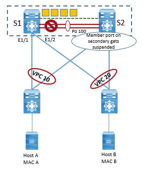
These vPC Primary and secondary is also very much used in case of vPC Peer-link failure which we will discuss in detail later in another section. But for overview, whenever peer-link goes down then on secondary peer switch, vPC shuts the vPC member ports and in addition to all SVI configured on that secondary peer- switch associated to vPC VLAN.
There is also concepts of operational role: Operational Primary and Operational Secondary.The Operational Primary and Operational Secondary role is driven by the real time behavior of peer-device.When the vPC domain is configured and is made operational, vPC role is always equal to operational role. And if in case of any event Secondary can become the Operational Primary in case Primary goes down and comes UP.

TABLE OF CONTENTS
- VPC Terminology & Deployment Scenarios
- VPC Configuration Best Practices
- VPC Consistency Check and failover Scenarios
- VPC Traffic Flows
- VPC in Mixed Chassis Mode
- Attaching Devices to VPC domain
- STP Behaviour in VPC
- VPC and L3 Design Scenarios
- Fex With vPC and ISSU
- VPC Enhancements
- Nexus 5500 & vPC
- LAB:Configuring vPC & its Components
- LAB: VPC Consistency Check and failover Scenarios
- LAB: Back to Back VPC
- OTV Terminology & Concepts
- OTV Control plane over Multicast & Unicast Infrastructure
- OTV Data Traffic
- OTV Advance Functions
- OTV Multi-Homing
- OTV FHRP Isolation & Stability Conditions
- OTV Single Edge Device – Multicast Mode Configuration
- OTV in Unicast Mode Configration Guidelines
- LAB OTV Configuration
RECENT POSTS
- Installing Context-Aware Network Access Control using Cisco ISE Policies
- Designing Network Access Control that is Scalable using Cisco ISE Architecture
- Enterprise Network Access Control and Policy Enforcement using Cisco ISE
- Secure Device Administration and Network Access Using AAA Architecture
- Designing Enterprise-Class Hybrid Cloud Connectivity Using AWS Networking Services
- Exploring Core AWS Networking and Messaging Concepts for Modern Cloud Architectures
- Understanding Key AWS Services for Modern Cloud Architectures
- Building a Strong AWS Foundation with Amazon S3, EC2, and Virtual Private Cloud
- Understanding the ENSDWI Course: Advanced Cisco SD-WAN (Viptela) Concepts
- A Complete Guide to the DCACI-A Course: Mastering Advanced Cisco ACI Concepts


LEAVE A COMMENT
Please login here to comment.