EMAIL SUPPORT
dclessons@dclessons.comLOCATION
USConfiguring Rapid PVST+
Rapid PVST+
Rapid PVST+ is IEEE 802.1w the default STP protocols enabled on all newly created VLAN on nexus 7K switches.
RSTP increase the traditional STP convergence time from almost 50 sec to less than 1 Sec. As soon as Rapid PVST+ is configured, it is enabled on per-VLAN basis and it can also be disabled on per-VLAN basis.
RSTP running on each VLAN has one Root Bridge and the selection criteria of Root Bridge, Root Port and designated port is same as traditional STP. Here we are not going to recalculate these ports as we assume that readers are well aware of these concepts in traditional Ethernet switch segments.
In RSTP, each designated ports sends out BPDU every 2 sec and if these BDDU are missed consecutive three times or if MAX age expires, the port immediately flushes all protocol information stored on it. Due to this short time BPDU loss allows quick failure detection and RSTP starts re-convergence. The BPDU version of RSTP is version 2 which means it can easily detects the connected legacy 802.1D Bridges.
Following are the ports used in RSTP:
Edge Ports: these ports transition immediately to forwarding states and is configured to those ports where end host are connected. These ports does not generate the TCN when topology changes.
Root Ports: It has shortest distance or cost to root bridge and when a new Root port is selected it blocks the old root ports and immediately transition new root port to forwarding state.
Point-to-Point Links: If a new port connected and becomes the DP port then it uses the proposal and agreement handshake to ensure loop free topology.
RSTP gets the rapid transition to forwarding states only on edge ports and Point to point link and only designated ports and root port generates TCN BPDU when they don’t receives the three consecutive BPDU from directly connected neighbor or after expiration of MAX age timer. And these ports send the configuration BPDU with TC bit set and these TCN BPDU is sent out all DP or Root port to reach to Root Bridge. The Port will send the BPDU with TC bit set as long as TC while timer runs on that port which is Hello time + 1 Sec.
When RSTP detects a topology change the RSTP takes the following action:
- It starts the TC while Timer whose value is equal to 2*Hello time for non-edge ports and DP ports.
- Flushes the MAC address associated with all these ports.
- Switch after receiving the TC BPDU, floods to all switch causes dynamic MAC address entries flush immediately on per port basis.
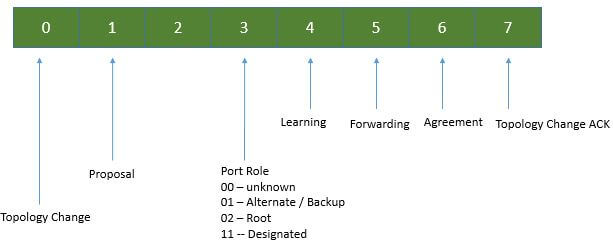
RSPT BPDU:
Rapid PVST+ and 802.1w uses all six bits of the flag byte for following:
- Role and state of port that has originated BPDU
- For Proposal and agreement handshake
Proposal and Agreement Handshake
In order to understand the Proposal and agreement handshake, refer the below topology:
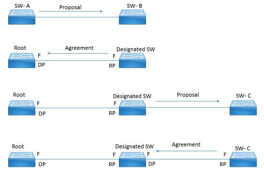
- In above figure SW-A is connected to SW-B via point to point link and at current stage all ports are in blocking state.
- Now let’s suppose that SW-A has priority smaller than SW-B due to which SW-A sends the Proposal message (configuration BPDU with Proposal Bit Set) to SW-B and proposing it as Designated Switch.
- SW-B receives the proposal and select the root port on which proposal was received and block all non-edge ports and sends the agreement message from Root Port.
- SW-A receive the Agreement message and make that designated port to forwarding state.
- Now Let’s Suppose at same time SW-C gets connected to SW-B and same process begins, SW-C select the port connected to SW-B as Root port and both ports between SW-B and SW-C moves to Forwarding state
- By this procedure any switch that connect to active topology will part of RSTP by providing loop free topology.

Comment
TABLE OF CONTENTS
- VPC Terminology & Deployment Scenarios
- VPC Configuration Best Practices
- VPC Consistency Check and failover Scenarios
- VPC Traffic Flows
- VPC in Mixed Chassis Mode
- Attaching Devices to VPC domain
- STP Behaviour in VPC
- VPC and L3 Design Scenarios
- Fex With vPC and ISSU
- VPC Enhancements
- Nexus 5500 & vPC
- LAB:Configuring vPC & its Components
- LAB: VPC Consistency Check and failover Scenarios
- LAB: Back to Back VPC
- OTV Terminology & Concepts
- OTV Control plane over Multicast & Unicast Infrastructure
- OTV Data Traffic
- OTV Advance Functions
- OTV Multi-Homing
- OTV FHRP Isolation & Stability Conditions
- OTV Single Edge Device – Multicast Mode Configuration
- OTV in Unicast Mode Configration Guidelines
- LAB OTV Configuration
RECENT POSTS
- Installing Context-Aware Network Access Control using Cisco ISE Policies
- Designing Network Access Control that is Scalable using Cisco ISE Architecture
- Enterprise Network Access Control and Policy Enforcement using Cisco ISE
- Secure Device Administration and Network Access Using AAA Architecture
- Designing Enterprise-Class Hybrid Cloud Connectivity Using AWS Networking Services
- Exploring Core AWS Networking and Messaging Concepts for Modern Cloud Architectures
- Understanding Key AWS Services for Modern Cloud Architectures
- Building a Strong AWS Foundation with Amazon S3, EC2, and Virtual Private Cloud
- Understanding the ENSDWI Course: Advanced Cisco SD-WAN (Viptela) Concepts
- A Complete Guide to the DCACI-A Course: Mastering Advanced Cisco ACI Concepts


LEAVE A COMMENT
Please login here to comment.