EMAIL SUPPORT
dclessons@dclessons.comLOCATION
USACI Hardware Installation
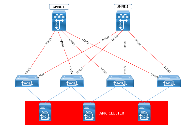
The Application Centric Infrastructure (ACI) Fabric hardware includes an Application Policy Infrastructure Controller (APIC) appliance (a cluster of three controllers), one or more leaf switches and one or more spine switches connected to each other .
The ACI fabric topology includes the following major components:
- Application Centric Infrastructure Controller (APIC) appliance (cluster of APICs)
- Switches that are used as Leaf switches are Cisco Nexus 93108TC-EX, 93108TC-FX, 93120TX, 93128TX, 93180LC-EX, 93180YC-EX, 93180YC-FX, 9332PQ, 9348GC-FXP, 9372PX, 9372PX-E, 9372TX, 9372TX-E, 9396PX, and 9396TX switches
- Switches that are used as Spine Switches are which are Cisco Nexus 9336PQ, 9364C, 9504, 9508, and 9516 switches.
The following figure shows how spine and leaf switches are connected to form the ACI Fabric
For APIC to configure we can use cluster of second generation Cisco UCS 220 M4 or we can also use cluster of First generation Cisco 220 M3. The Image of these Servers are secured with Certificates, APIC Product ID (PID) and also with Trusted Platform Module (TPM). There are two modes to configure the APIC controller:
For Large cluster : Cluster of three Cisco APIC second generation controllers with large size CPU, hard drive, and memory configurations for more than 1000 edge ports.
For Medium cluster: Cluster of three Cisco APIC second generation controllers with medium size CPU, hard drive, and memory configurations for up to 1000 edge ports.
Connection Features on a Second-Generation APIC Controller is shown as follows.
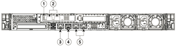
- It has Virtual Interface Card (VIC) for either optical (VIC1225) connections or 10GBASE-T (VIC1225T) connections
- To provide connection to downlink port on TOR Switches it has two fiber optic or 10GBASE-T ports
- It has 1-Gigabit Ethernet as Cisco Integrated Management Controller (CIMC) port to provide a console ( connection) connection
- A Console port for a direct connection to a console if you have to configure device via Console.
- It has Out-of-band management ports for OOB connection and it cannot be used as CIMC ports except when using the Shared_LOM mode
Connecting Leaf Switches to APICs
In order to create the ACI fabric ACI-mode leaf switches must be connected to each APIC. The cable used to connect to Leaf and APIC depends upon the type of virtual interface card (VIC) installed on the APIC.
VIC card capabilities of APIC Controller.
- The VIC1225 module supports optical SFP/SFP+ transceivers and to connect it we use optical fiber cables. The following switches which has optical downlink ports are Cisco Nexus 93180LC-EX, 93180YC-EX, 93180YC-FX, 9332PQ, 9348GC-FXP, 9372PX, 9372PX-E, and 9396PX.
- The VIC1225T module has copper connection capability and to provide connectivity we use copper connectors and copper cables. The following switches which has copper downlink ports are Cisco Nexus 93108TC-EX, 93128TX, 9348GC-FXP,9372TX, 9372TX-E,93108TC-FX, 93120TX,and 9396TX switches.
Connecting Leaf Switches to Spine Switches
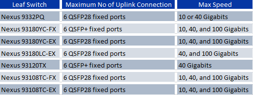
For optimal forwarding between endpoints, you must connect each leaf switch (Cisco Nexus 93108TC-EX, 93108TC-FX, 93120TX, 93128TX, 93180LC-EX, 93180YC-EX, 93180YC-FX, 9332PQ, 9372PX, 9372PX-E, 9372TX, 9372TX-E, 9396PX, or 9396TX) to every spine switch (Cisco Nexus 9336PQ, 9504, 9508, or 9516) in the same ACI fabric. The following table provides the number of ports which can be used to connect leaf switches and the supported speeds for those ports
The leaf and spine switches in the fabric must be fully installed in their racks and grounded and is powered on.
Setting up the APIC
There are some options available to configure APIC .
- CIMC : You can either use the CIMC address that you have setup on the APIC to connect to it over the network
- Console : ( via Serial Connection )
Here we will discuss how to configure APIC via Console.
When the APIC is started first time , you will see a series of initial setup options on APIC console. For some option you can press Enter which can let you choose default setting and if any point of time while setup configuration you can restart the setup dialog by pressing Ctrl-C.
Now if have connected RJ-45 cable on console port, in this case first you should connect to CIMC using SSH and enable Serial over LAN port by using the following parameters:
- Set Enabled to Yes
- Commit
- Exit
Once this has been enabled , use command "connect host" to get access to console. If you have connected the serial port then disconnect it or make sure connected device has proper configuration
Setup for Active and Standby APIC:
In large DC infrastructure , we should have atleast 3 Controller in Active Active Mode and one another APIC Controller in standby mode, and in it can be scaled up to 5 or 7 APIC controller based on APIC Software Version, and When any one of the Active controller fails , the standby controller is promoted to take part in remaining active controller cluster.
And if all three Active controller is working properly , the standby controller would only participate automatic software upgrade but does not hold any configuration. To take Standby APIC in active role , admin needs to promote it to active with vaild APIC id number. This function starts from APIC 2.2 release onwards.
Following option are used when configuring Active APIC via Console.
Fabric name: ACI Fabric1
Fabric ID: 1
Number of active controllers: 3, When setting up APIC in an active-standby mode, you must have at least 3 active APICs in a cluster.
POD ID: 1
Standby controller: No ( For Standby APIC it will be yes).
Controller ID: Valid range: 1-19, Unique ID number for the active APIC instance.
Active controller name: apic1
IP address pool for tunnel endpoint addresses: 10.0.0.0/16
The subnet allocated here will be used for the infrastructure virtual routing and forwarding (VRF) only. And this subnet should not overlap with any other routed subnets in your network to avoid subnet clash . Subnet /23 is the The minimum supported subnet for a 3 APIC cluster and If you are using Release 2.0(1) the minimum supported subnet is /22.
VLAN ID for infrastructure network: This is the Infrastructure VLAN for APIC-to-switch communication including virtual switches. You should reserve this VLAN for APIC use only. This infrastructure VLAN ID must not be used elsewhere in your environment and must not overlap with any other reserved VLANs on any other platforms.
IP address pool for bridge domain multicast address (GIPo): 225.0.0.0/15 . Valid range for GIPo : 225.0.0.0/15 to 231.254.0.0/15, prefixlen must be 15 (128k IPs).
Management interface speed/duplex mode: auto
Strong password check: Y
Example

Comment
TABLE OF CONTENTS
- ACI Initial Fabric Configuration
- ACI Configure Tenant VRF & Bridge Domain
- ACI Configure Filters and Contracts
- ACI Configure Three-Tier Application Profile
- ACI Configure Baseline Interface Policies
- ACI Integration with VMWARE
- ACI Inter Tenant Connectivity
- ACI Extend Bridge Domain by External Layer 2 Connection
- ACI External Network Connectivity to External Switch via Trunk
- ACI Static Routing for External Layer 3 Connectivity
- ACI OSPF Routing for External Layer 3 Connectivity
- ACI EIGRP Routing for External Layer 3 Connectivity
- ACI EBGP Routing for External Layer 3 Connectivity
- IPN Configuration
- ACI Multipod Overview
- ACI Multi-Pod Building Control Plane
- ACI Multi-Pod Data Traffic Flow
- Multi-Pod Connectivity via External L3
- Host Tracking Subnet Check & Limit IP Learning
- Service Graph Introduction
- BD VRF & EPG Design consideration – Service Chaining
- IP Routing & VRF Design Consideration – Service Chaining
- L3Out for Routing to L4-L7 Devices
- Routed Mode ( Go-To mode ) for L4-L7 Appliance
- Transparent & One ARM mode for L4-L7 Appliance
- Policy Based Redirect in ACI
RECENT POSTS
- Installing Context-Aware Network Access Control using Cisco ISE Policies
- Designing Network Access Control that is Scalable using Cisco ISE Architecture
- Enterprise Network Access Control and Policy Enforcement using Cisco ISE
- Secure Device Administration and Network Access Using AAA Architecture
- Designing Enterprise-Class Hybrid Cloud Connectivity Using AWS Networking Services
- Exploring Core AWS Networking and Messaging Concepts for Modern Cloud Architectures
- Understanding Key AWS Services for Modern Cloud Architectures
- Building a Strong AWS Foundation with Amazon S3, EC2, and Virtual Private Cloud
- Understanding the ENSDWI Course: Advanced Cisco SD-WAN (Viptela) Concepts
- A Complete Guide to the DCACI-A Course: Mastering Advanced Cisco ACI Concepts


LEAVE A COMMENT
Please login here to comment.