EMAIL SUPPORT
dclessons@dclessons.comLOCATION
USVPC for ESXi-1 & ESXi-2
We all know, that VPC is used to pair two Nexus switches to act as one logical node, which provides redundancy, full BW utilization to end host connecting to the VPC.
Below are some differences that ACI has with respect to traditional NX-OS Switches.
No dedicated Peer-Link: In ACI, fabric provides the transport path to VPC peers to exchange information & State so that traffic can move from one leaf to another using VXLAN Overlay.
VPC Peer State Protocol: In NX-OS, CFS is used to share MAC information and state between Peer switches. But in ACI, VPC uses ZeroMQ which is an open-source messaging library that uses TCP socket as transport layer. ZeroMQ is used to synchronize state of the peer if any protocol requires like IGMP or End Point Manager (EPM)
Peer Keep Alive: unlike in NX-OS, In ACI VPC there is no physical link for Peer Keep alive link. Members of the VPC domain, have a unique tunnel interface that points to its member. This tunnel contains the destination VTEP IP of peer switch.
Now due to any reason, if route to that VTEP is removed from Overlay1 routing table, then VPC manager in ACI will bring down the ZeroMQ socket. When the route came back, the tunnel comes UP, Socket is established again.
When creating a VPC domain, both peer switch must be in same switch generation as per below 9300 platform product line.
- Generation 1: Cisco Nexus 9300 switches without EX or FX, example: 9372PX, 93210TX, 9332PQ
- Generation 2: Cisco Nexus 9000 Switches with EX or FX, such as 93180-YC-EX, 93108TC-EX, 93108TC-FX
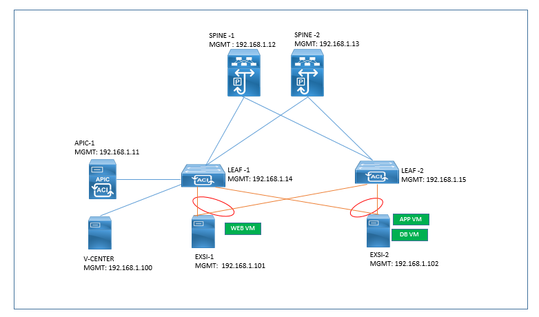
The collective goal of labs 3 is to create VPCs between Leaf1 (node-101) and Leaf2 (node-102) in order to connect to servers ESX-1 and ESX-2.
Physical Topology:
Solution : There will be a series of elements which need to be created first before we can create the VPCs. The steps are:
- Create Interface Policies
- Create Interface Policy Group
- Create Interface Profiles (interface selectors)
- Create Switch Profile
- Create VPC Explicit Protection Group
Create Interface Policies
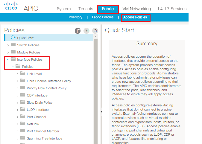
- From the main menu, choose “Fabric”
- From the sub-menu, Choose “Access Policies”
- From the left menu, expand “Interfaces Policies”
- Then, expand “Policies” to show a list of policies that are available to be configured
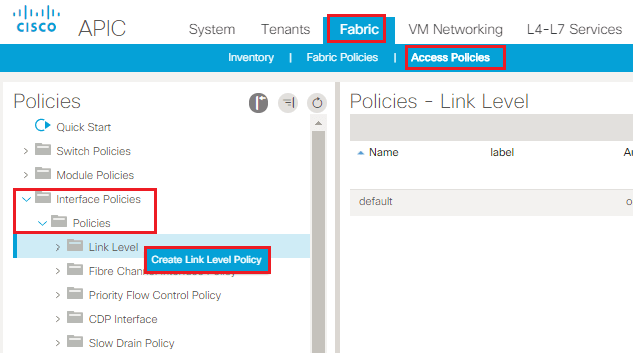
Creating Link Level Policy
- Highlight “Link Level” and right-click. Choose “Create Link Level Policy”
- A pop-up window will appear to create a Link Level Policy
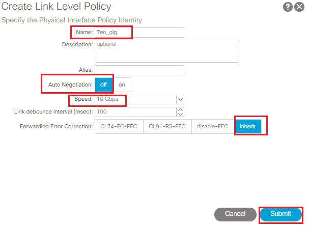
- In the Create Link Level Policy Dialogue box. For Name, type “ten_gig”
- For Auto Negotiation, choose “off”
- For speed, click the drop-down and choose “10 Gbps”
- Click “Submit”
Create LLDP Policy
From the Interface Policies section, highlight “LLDP Interfaces”, right click and choose “Create LLDP Interface Policy”
- A pop-up window will appear to create a LLDP Interface Policy
- For Name, type “LLDP-Enable”
- The default for Receive State is already set to enable, we will accept the default.
- The default for Transmit State is already set to enable, we will accept the default
- Click “Submit”
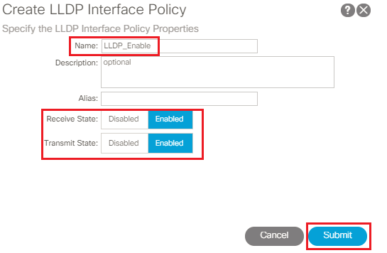

TABLE OF CONTENTS
- ACI Initial Fabric Configuration
- ACI Configure Tenant VRF & Bridge Domain
- ACI Configure Filters and Contracts
- ACI Configure Three-Tier Application Profile
- ACI Configure Baseline Interface Policies
- ACI Integration with VMWARE
- ACI Inter Tenant Connectivity
- ACI Extend Bridge Domain by External Layer 2 Connection
- ACI External Network Connectivity to External Switch via Trunk
- ACI Static Routing for External Layer 3 Connectivity
- ACI OSPF Routing for External Layer 3 Connectivity
- ACI EIGRP Routing for External Layer 3 Connectivity
- ACI EBGP Routing for External Layer 3 Connectivity
- IPN Configuration
- ACI Multipod Overview
- ACI Multi-Pod Building Control Plane
- ACI Multi-Pod Data Traffic Flow
- Multi-Pod Connectivity via External L3
- Host Tracking Subnet Check & Limit IP Learning
- Service Graph Introduction
- BD VRF & EPG Design consideration – Service Chaining
- IP Routing & VRF Design Consideration – Service Chaining
- L3Out for Routing to L4-L7 Devices
- Routed Mode ( Go-To mode ) for L4-L7 Appliance
- Transparent & One ARM mode for L4-L7 Appliance
- Policy Based Redirect in ACI
RECENT POSTS
- Installing Context-Aware Network Access Control using Cisco ISE Policies
- Designing Network Access Control that is Scalable using Cisco ISE Architecture
- Enterprise Network Access Control and Policy Enforcement using Cisco ISE
- Secure Device Administration and Network Access Using AAA Architecture
- Designing Enterprise-Class Hybrid Cloud Connectivity Using AWS Networking Services
- Exploring Core AWS Networking and Messaging Concepts for Modern Cloud Architectures
- Understanding Key AWS Services for Modern Cloud Architectures
- Building a Strong AWS Foundation with Amazon S3, EC2, and Virtual Private Cloud
- Understanding the ENSDWI Course: Advanced Cisco SD-WAN (Viptela) Concepts
- A Complete Guide to the DCACI-A Course: Mastering Advanced Cisco ACI Concepts


LEAVE A COMMENT
Please login here to comment.