EMAIL SUPPORT
dclessons@dclessons.comLOCATION
USMulti-Site Data Plane Communication
Once, Endpoint information is exchanged between sites, VXLAN data Plane is used to send and receive intersite Layer 2 and Layer 3 Communication.
Now we are going to discuss how layer 2 and Layer 3 data traffic flows inside Multi-Site environment.
Layer 2 BUM traffic across Sites
In Cisco ACI Multi-Site design, there is need to enable ingress replication function on source VTEP (Spines), doing so, it will create multiple unicast copies of each BUM traffic and send it to all remote VTEPs.
The replication of Layer 2 BUM traffic across sites is only possible for those BD only , which have been stretched across sites and a flag named ‘intersite BUM traffic allow ‘ is enabled on it.
Below describes the intersite forwarding behavior of three types of BUM traffic, when BUM is allowed across sites for a given BD.
Layer 2 Broadcast Frame: These are always forwarded across sites, example is ARP Traffic
Layer 2 Unknown Unicast frame: These traffic are not flooded, instead forwarded in unicast mode, by assuming that destination MC address is known in COOP database of local spine table.
Multicast Frame: For the intra bridge domain layer 3 Multicast frame and Layer 2 Multicast frame, the same forwarding behavior is applied. When BUM forwarding is enabled for particular BD, traffic is forwarded across sites.
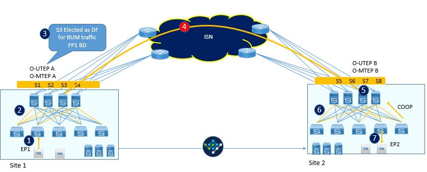
Let’s understand step by step, how Layer 2 BUM traffic is forwarded across sites.
- EP1 belongs to specific BD generates Layer 2 BUM traffic
- Based on BD configuration, frame is encapsulated in VXLAN and is then sent to specific Multicast address (GIPo), associated to that particular BD, so that it can reach to all leafs and spine.
- Here one of the spine node connected to intersite network is elected as designated forwarder for that particular BD, and this Designated forwarded upon receipt of BUM frame, make its multiple copies and send it to all remote sites, with source address of its own O-UTEP and destination IP address as O-MTEP.
- When one of the spine nodes receives this traffic, here translation of VNID value contained in VXLAN header took place with the locally significant VNID values, which is associated to same BD.
- Now this traffic is send to site using the site Multi-destination tree defined for that bridge domain.
- Traffic then reached to all spines and to all leafs including those leaf on which endpoint is connected.
- Once all leafs receives that frame, it will use the remote location of EP1 Site and store in its database. Now using this information, EP2 will replay ARP unicast frame for that particular ARP request and then further forwarded by Spine of site 2 to EP1 Sites.
Below figure describes Layer 2 BUM traffic across sites.
Intrasubnet unicast communication across sites
In this scenario, let’s understand, how ARP address works, in this there are two different scenarios:
Option1: When ARP flowing is enabled in Bridge domain: This scenario work well when BD is stretched across site and BUM flooding is enabled. In this case traffic behavior will be same like discussed in just above section.
Here once ARP reply is received by leaf node of Site 1, it will learn the EP2 site information. It should be noted that ARP flooding is enabled for BD only on MSO.
Option 2: When ARP flowing is disabled on Bridge Domain: This is the default configuration for stretched BD domain configured on MSO with BUM forwarding disabled.
Below is the steps for it.
EP1 sends the ARP request for EP2 IP address.
Once this ARP request is intercepted by Local leaf and, if EP2 information is not available to it, then this request is encapsulated to Proxy Anycast address of spines of local sites.
Now when one of the spines receives the ARP request from Local Leaf, Spine will check the COOP database, that weather it has information available for EP2, which is shared by MP-BGP EVPN protocol.
Case a) Local Spine knows the information of EP2
- Let’s suppose that spine knows the information of EP2 and its entry is found in its local database that is O-UTEP address of EP2.
- Spines encapsulates this packet with source Address of its Local O-UTEP and Destination address of EP2 O-UTEP.
- When this VXLAN encapsulated packet is received by one of the Spine in remote site, it translates the original VNID and class-ID to locally significant one and send this ARP request to local Leaf Connected to EP2.
- Leaf Nodes receives this packet and decapsulates it, learns the class-ID and site location information for remote site endpoint EP2.
- Finally Frame is sent to EP2 connected interface.
Case b) Local Spine does not know the Information of EP2.
When Local Spine upon receipt of ARP request, consults to it local COOP DB, and do not find its information, then a process called as ARP glean process is followed by Spine , Inorder to get the EP2 information.

Comment
TABLE OF CONTENTS
- ACI Initial Fabric Configuration
- ACI Configure Tenant VRF & Bridge Domain
- ACI Configure Filters and Contracts
- ACI Configure Three-Tier Application Profile
- ACI Configure Baseline Interface Policies
- ACI Integration with VMWARE
- ACI Inter Tenant Connectivity
- ACI Extend Bridge Domain by External Layer 2 Connection
- ACI External Network Connectivity to External Switch via Trunk
- ACI Static Routing for External Layer 3 Connectivity
- ACI OSPF Routing for External Layer 3 Connectivity
- ACI EIGRP Routing for External Layer 3 Connectivity
- ACI EBGP Routing for External Layer 3 Connectivity
- IPN Configuration
- ACI Multipod Overview
- ACI Multi-Pod Building Control Plane
- ACI Multi-Pod Data Traffic Flow
- Multi-Pod Connectivity via External L3
- Host Tracking Subnet Check & Limit IP Learning
- Service Graph Introduction
- BD VRF & EPG Design consideration – Service Chaining
- IP Routing & VRF Design Consideration – Service Chaining
- L3Out for Routing to L4-L7 Devices
- Routed Mode ( Go-To mode ) for L4-L7 Appliance
- Transparent & One ARM mode for L4-L7 Appliance
- Policy Based Redirect in ACI
RECENT POSTS
- Installing Context-Aware Network Access Control using Cisco ISE Policies
- Designing Network Access Control that is Scalable using Cisco ISE Architecture
- Enterprise Network Access Control and Policy Enforcement using Cisco ISE
- Secure Device Administration and Network Access Using AAA Architecture
- Designing Enterprise-Class Hybrid Cloud Connectivity Using AWS Networking Services
- Exploring Core AWS Networking and Messaging Concepts for Modern Cloud Architectures
- Understanding Key AWS Services for Modern Cloud Architectures
- Building a Strong AWS Foundation with Amazon S3, EC2, and Virtual Private Cloud
- Understanding the ENSDWI Course: Advanced Cisco SD-WAN (Viptela) Concepts
- A Complete Guide to the DCACI-A Course: Mastering Advanced Cisco ACI Concepts


LEAVE A COMMENT
Please login here to comment.