EMAIL SUPPORT
dclessons@dclessons.comLOCATION
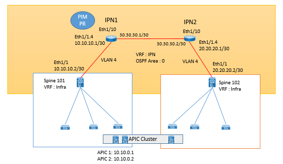
USIPN Configuration
We need to follow below configuration in ACI as well as on IPN in order to make out ACI fabric as Multi-Pod.
Configuration on ACI:
Step 1. Create a VLAN pool and add VLAN 4. (VLAN 4 is the only VLAN used to peer with IPN devices.)
Step 2. Create an external routed domain. Associate the newly created VLAN pool with this domain.
Step 3. Create an AAEP and associate it with the external routed domain.
Step 4. Create interface and switch policies under the Access Policy tab in the APIC to program ports Eth1/1 on Spine-101 and Spine-102 to peer with IPN devices. Associate the AAEP to the spine interface policy groups.
Step 5. Create an external routed network (L3Out) under the Infra tenant:
- Associate the external routed domain.
- Select OSPF regular area 0. (The OSPF area could be other than area 0. OSPF is the only protocol supported while peering spines with IPN devices. Any routing protocol or static routes within the IPN are supported.)
- Create a routed sub-interface using VLAN 4 as the transport link to route peer with IPN devices using OSPF.
Configuration on IPN Devices
Step1 : Enable following feature on Nexus device who will be working as IPN
feature ospf feature pim feature dhcp feature lldp !
Step2:Create VRF Instance for IPN traffic, though it is not required but is recommended.
vrf context IPN !
Step3: Configure MTU 9150 to Interfaces and on System itself.
system jumbomtu 9216 ! On Nexus, System Jumbo MTU size of 9216 is enabled by default ! interface Ethernet1/10 description "Interface connected to Spine" no switchport mtu 9150 no shutdown
Step 4: Configure PIM BiDir

Comment
TABLE OF CONTENTS
- ACI Initial Fabric Configuration
- ACI Configure Tenant VRF & Bridge Domain
- ACI Configure Filters and Contracts
- ACI Configure Three-Tier Application Profile
- ACI Configure Baseline Interface Policies
- ACI Integration with VMWARE
- ACI Inter Tenant Connectivity
- ACI Extend Bridge Domain by External Layer 2 Connection
- ACI External Network Connectivity to External Switch via Trunk
- ACI Static Routing for External Layer 3 Connectivity
- ACI OSPF Routing for External Layer 3 Connectivity
- ACI EIGRP Routing for External Layer 3 Connectivity
- ACI EBGP Routing for External Layer 3 Connectivity
- IPN Configuration
- ACI Multipod Overview
- ACI Multi-Pod Building Control Plane
- ACI Multi-Pod Data Traffic Flow
- Multi-Pod Connectivity via External L3
- Host Tracking Subnet Check & Limit IP Learning
- Service Graph Introduction
- BD VRF & EPG Design consideration – Service Chaining
- IP Routing & VRF Design Consideration – Service Chaining
- L3Out for Routing to L4-L7 Devices
- Routed Mode ( Go-To mode ) for L4-L7 Appliance
- Transparent & One ARM mode for L4-L7 Appliance
- Policy Based Redirect in ACI
RECENT POSTS
- Installing Context-Aware Network Access Control using Cisco ISE Policies
- Designing Network Access Control that is Scalable using Cisco ISE Architecture
- Enterprise Network Access Control and Policy Enforcement using Cisco ISE
- Secure Device Administration and Network Access Using AAA Architecture
- Designing Enterprise-Class Hybrid Cloud Connectivity Using AWS Networking Services
- Exploring Core AWS Networking and Messaging Concepts for Modern Cloud Architectures
- Understanding Key AWS Services for Modern Cloud Architectures
- Building a Strong AWS Foundation with Amazon S3, EC2, and Virtual Private Cloud
- Understanding the ENSDWI Course: Advanced Cisco SD-WAN (Viptela) Concepts
- A Complete Guide to the DCACI-A Course: Mastering Advanced Cisco ACI Concepts


LEAVE A COMMENT
Please login here to comment.