EMAIL SUPPORT
dclessons@dclessons.comLOCATION
USRouted Mode ( Go-To mode ) for L4-L7 Appliance
There are two method to deploy L4-L7 devices in ACI:
- Deploy L4-L7 device (service graph) in routed mode with NAT enabled
- Deploy L4-L7 device (service graph) in routed mode and used L3Out with static or dynamic routing to connect to L4-L7 device
When we use L3out to connect the L4-L7 device to ACI, it requires two BD, one to be used for Client side and another to be used for Server side interface. This Server side interface also cats as default gateway for all the Servers. Routing from outside to inside can be done by fabric itself or by external router.
Following are design option while using Routed mode service graph
- Routed mode service graph with outside L2 BD
- Routed mode Service Graph with L3Out and NAT
- Routed Mode Service Graph with PBR
Here we will be discussing the above two mostly.
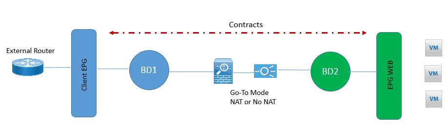
Routed mode service graph with outside L2 BD: In this design the external router is used to provide gateway to service and the FW or LB can used NAT or also NO NAT
In below figure, both inside and outside interface are connected to two BD which are L2 mode only and BD are attached to VRF only to follow the object model. In this design, only create contracts between Client EPG and Server side EPG which will achieve the service graph configuration.
Routed mode with NAT: if the service device is using NAT to translate the IP address of servers like LB, a VRF instance can be used to provide routing from outside to service device and this can be done by L3Out.
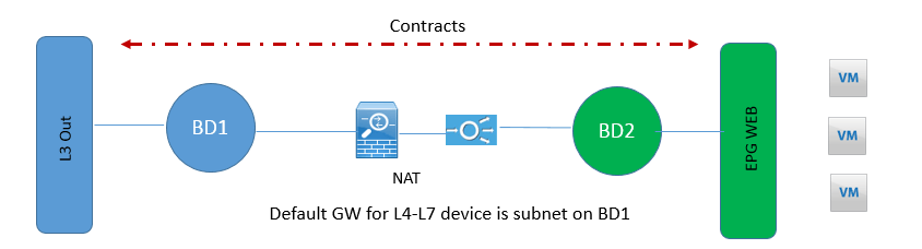
In above figure L3out is attached to LB, and the Internal BD2 is not providing routing to servers. Now VRF instance is attached to internal BD only to define object model. L4-L7 devices are providing Gateway for servers. Static routing on L4-L7 may be used to provide routing to outside network from L4-L7 device. Outside BD is providing routing to service appliance and is GW for service appliance. VRF instance is attached to outside BD and routing is being performed via L3Out.
Now to make BD1 learn only NAT IP address of servers, configure Limit IP learning to subnet.
Now in this case service graph configuration is achieved by using contracts between Internal EPG and L3Out EPG.
Routed Mode with L3Out routing to L4-L7 device: In this design there are two VRF used, one VRF provides route peering to outside or client interface of FW or LB and another VRF will be used for server Farm. In this design only BD to used for Server farm and this BD will not be configured for Routing and the server GW would be Internal Interface of FW or LB.
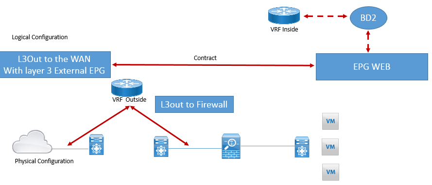
VRF used for outside will be having two interface , one configured for routing to WAN and another routing to FW. Contracts will be configured between L3Out EPG and Server side EPG.
Comment
TABLE OF CONTENTS
- ACI Initial Fabric Configuration
- ACI Configure Tenant VRF & Bridge Domain
- ACI Configure Filters and Contracts
- ACI Configure Three-Tier Application Profile
- ACI Configure Baseline Interface Policies
- ACI Integration with VMWARE
- ACI Inter Tenant Connectivity
- ACI Extend Bridge Domain by External Layer 2 Connection
- ACI External Network Connectivity to External Switch via Trunk
- ACI Static Routing for External Layer 3 Connectivity
- ACI OSPF Routing for External Layer 3 Connectivity
- ACI EIGRP Routing for External Layer 3 Connectivity
- ACI EBGP Routing for External Layer 3 Connectivity
- IPN Configuration
- ACI Multipod Overview
- ACI Multi-Pod Building Control Plane
- ACI Multi-Pod Data Traffic Flow
- Multi-Pod Connectivity via External L3
- Host Tracking Subnet Check & Limit IP Learning
- Service Graph Introduction
- BD VRF & EPG Design consideration – Service Chaining
- IP Routing & VRF Design Consideration – Service Chaining
- L3Out for Routing to L4-L7 Devices
- Routed Mode ( Go-To mode ) for L4-L7 Appliance
- Transparent & One ARM mode for L4-L7 Appliance
- Policy Based Redirect in ACI
RECENT POSTS
- Installing Context-Aware Network Access Control using Cisco ISE Policies
- Designing Network Access Control that is Scalable using Cisco ISE Architecture
- Enterprise Network Access Control and Policy Enforcement using Cisco ISE
- Secure Device Administration and Network Access Using AAA Architecture
- Designing Enterprise-Class Hybrid Cloud Connectivity Using AWS Networking Services
- Exploring Core AWS Networking and Messaging Concepts for Modern Cloud Architectures
- Understanding Key AWS Services for Modern Cloud Architectures
- Building a Strong AWS Foundation with Amazon S3, EC2, and Virtual Private Cloud
- Understanding the ENSDWI Course: Advanced Cisco SD-WAN (Viptela) Concepts
- A Complete Guide to the DCACI-A Course: Mastering Advanced Cisco ACI Concepts


LEAVE A COMMENT
Please login here to comment.