EMAIL SUPPORT
dclessons@dclessons.comLOCATION
USLAB: ACI Extend Bridge Domain by External Layer 2 Connection
Topology:
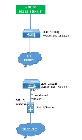
TASK: Follow the below following task to configure External Layer 2 Connectivity and extending Bridge Domain.
TASK1: Configure AEP and Switch Policy on which External Switch is connected.
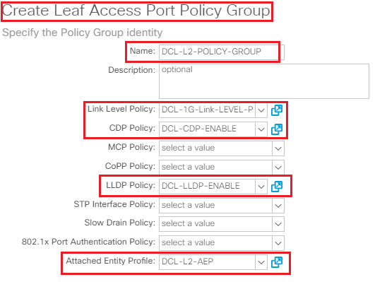
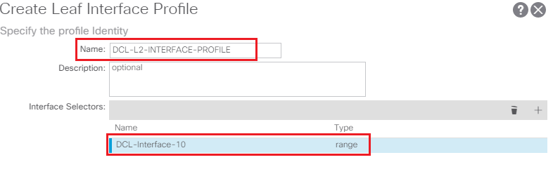
- Create the Attachable Access Entity Profile named DCL-L2-AEP and associate Interface policy Group named DCL-L2-POLICY-GROUP and call 1G Link Level Policy, CDP enable policy, LLDP enable Policy create Interface Profile named DCL-L2-INTERFACE-PROFILE and associate with it.
- Configure Switch Profile Policy and select Leaf 102 and port 1/10 over which external Switch is connected.
TASK2: Configure VLAN Pool for External Bridge Domain.
- Configure VLAN Pool named DCL-EXTERNAL-BD-VLAN-POOL
- Use static allocation and use VLAN 211.
TASK3: Configure External Bridge Domain or Layer 2 Domain.
- Configure Layer 2 Bridge Domain named DCL-EXTERNAL-BRIDGE DOMAIN
- Associate AEP DCL-L2-AEP with it
- Use VLAN Pool DCL-EXTERNAL-BD-VLAN-POOL in it.
TASK4: Configure External Bridge Network.
- Configure External Bridge Network or Layer 2 Outside network named DCL-EXTERNAL-BRIDGE-NET
- Associate Layer 2 Bridge Domain named DCL-EXTERNAL-BRIDGE DOMAIN
- Associate Bridge Domain DCLessons_BD with encap 211
- Use Path type Port and select path 102/eth1/10
- Create External network EPG named DCL-EXTERNAL-EPG
TASK5: Configure Contracts between Web_EPG and External Network
- Use Contracts named DCLessons-Contract-ANY which was created earlier in section as provided side.
- And on EPG named DCL-EXTERNAL-EPG use contracts DCLessons-Contract-ANY at consumer side.
Solution:
TASK1: Configure AEP and Switch Policy on which External Switch is connected.
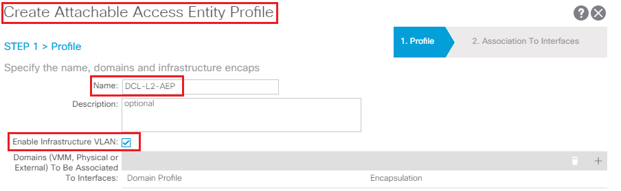
- Create the Attachable Access Entity Profile named DCL-L2-AEP and associate Interface policy Group named DCL-L2-POLICY-GROUP and call 1G Link Level Policy, CDP enable policy, LLDP enable Policy
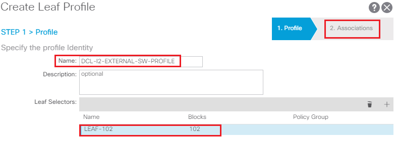
- Configure Switch Profile Policy and select Leaf 102 and port 1/10 over which external Switch is connected.
Create the Attachable Access Entity Profile named DCL-L2-AEP and associate Interface policy Group named DCL-L2-POLICY-GROUP and call 1G Link Level Policy, CDP enable policy, LLDP enable Policy after creating these.
- Click to Global Policies | Attachable Access Entity Profiles.
- Right-click on the Attachable Access Entity Profiles and then select Create Attachable Access Entity Profile
- Create Attachable Access Entity Profile named DCL-L2-AEP
- Click the NEXT button. In STEP 2 > Association to Interfaces, do not make any changes.
Associate Interface policy Group named DCL-L2-POLICY-GROUP and call 1G Link Level Policy, CDP enable policy, and LLDP enable Policy after creating these. In this we have already learned to create the above asked policies so we are not going to cover it end to end and here only screen shots are given.
Enable Policy create Interface Profile named DCL-L2-INTERFACE-PROFILE and associate above policy with it also Configure Switch Profile Policy and select Leaf 102 and port 1/10 over which external Switch is connected.

Comment
TABLE OF CONTENTS
- ACI Initial Fabric Configuration
- ACI Configure Tenant VRF & Bridge Domain
- ACI Configure Filters and Contracts
- ACI Configure Three-Tier Application Profile
- ACI Configure Baseline Interface Policies
- ACI Integration with VMWARE
- ACI Inter Tenant Connectivity
- ACI Extend Bridge Domain by External Layer 2 Connection
- ACI External Network Connectivity to External Switch via Trunk
- ACI Static Routing for External Layer 3 Connectivity
- ACI OSPF Routing for External Layer 3 Connectivity
- ACI EIGRP Routing for External Layer 3 Connectivity
- ACI EBGP Routing for External Layer 3 Connectivity
- IPN Configuration
- ACI Multipod Overview
- ACI Multi-Pod Building Control Plane
- ACI Multi-Pod Data Traffic Flow
- Multi-Pod Connectivity via External L3
- Host Tracking Subnet Check & Limit IP Learning
- Service Graph Introduction
- BD VRF & EPG Design consideration – Service Chaining
- IP Routing & VRF Design Consideration – Service Chaining
- L3Out for Routing to L4-L7 Devices
- Routed Mode ( Go-To mode ) for L4-L7 Appliance
- Transparent & One ARM mode for L4-L7 Appliance
- Policy Based Redirect in ACI
RECENT POSTS
- Installing Context-Aware Network Access Control using Cisco ISE Policies
- Designing Network Access Control that is Scalable using Cisco ISE Architecture
- Enterprise Network Access Control and Policy Enforcement using Cisco ISE
- Secure Device Administration and Network Access Using AAA Architecture
- Designing Enterprise-Class Hybrid Cloud Connectivity Using AWS Networking Services
- Exploring Core AWS Networking and Messaging Concepts for Modern Cloud Architectures
- Understanding Key AWS Services for Modern Cloud Architectures
- Building a Strong AWS Foundation with Amazon S3, EC2, and Virtual Private Cloud
- Understanding the ENSDWI Course: Advanced Cisco SD-WAN (Viptela) Concepts
- A Complete Guide to the DCACI-A Course: Mastering Advanced Cisco ACI Concepts


LEAVE A COMMENT
Please login here to comment.