EMAIL SUPPORT
dclessons@dclessons.comLOCATION
USLAB: Configure - Logical Devices, Device Profiles, and Interface Maps
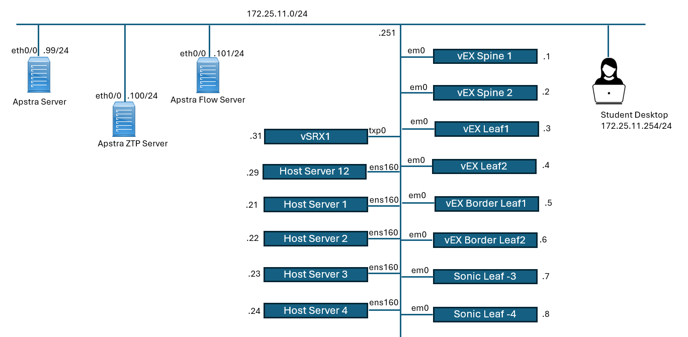
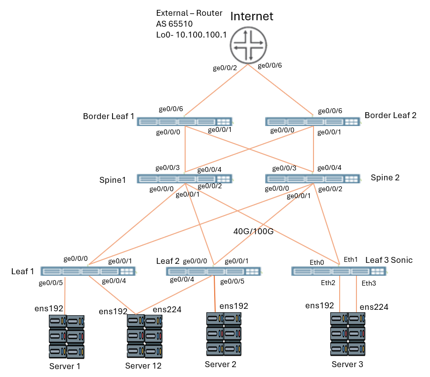
Physical Topology
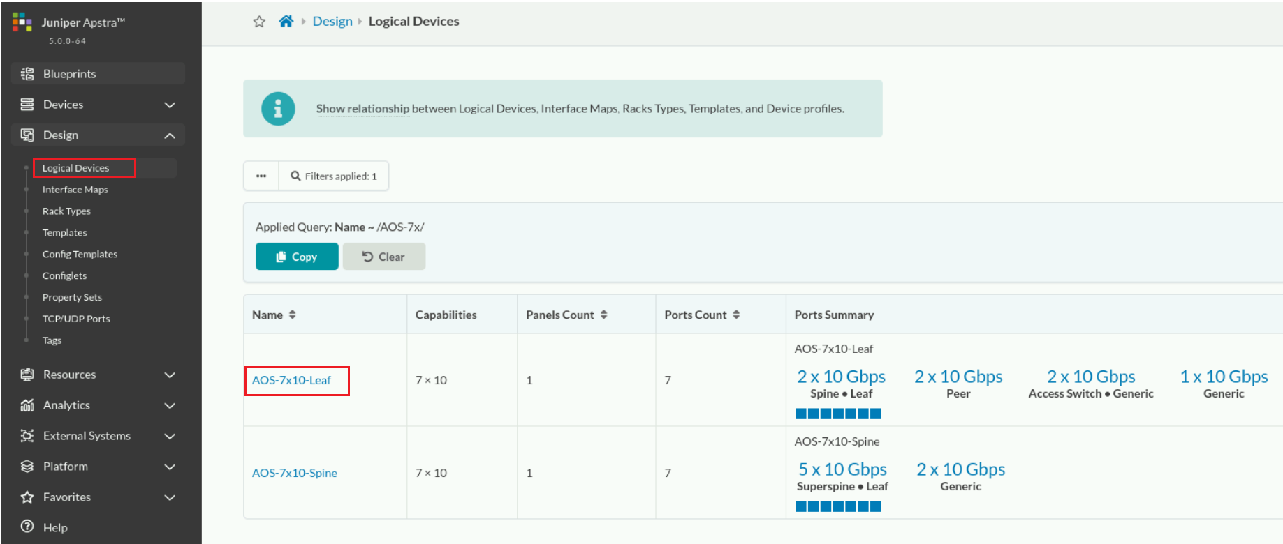
Navigate to Design > Logical Devices.
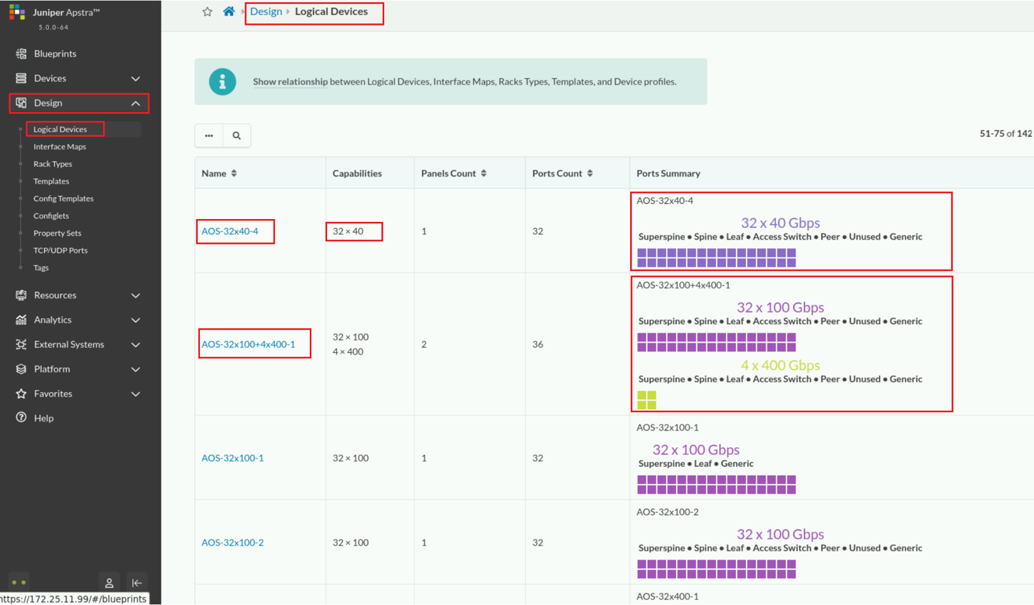
The capability of the logical device is 32x100Gbps, and it has one panel. This means that it has a single line-card or slot. That single line-card has 32, 100Gbps interfaces available to use.
The Ports Summary shows a single port group containing all 32 ports. You can use the ports in the port group to connect to superspine, leaf, and generic devices.
Because this logical device can only connect to superspine, leaf, and generic devices, it is highly probable that this logical device can represent a potential spine node in your network.
This logical device does not have any ports that you can connect to a spine node, it probably will not be used to represent a leaf node.
Use the query to find and select the name of the AOS-7x10-Leaf logical device. Click the magnifying glass icon and enter the name AOS-7x, click Apply, then click the name AOS-7x10-Leaf .
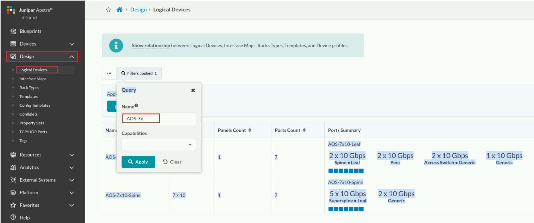
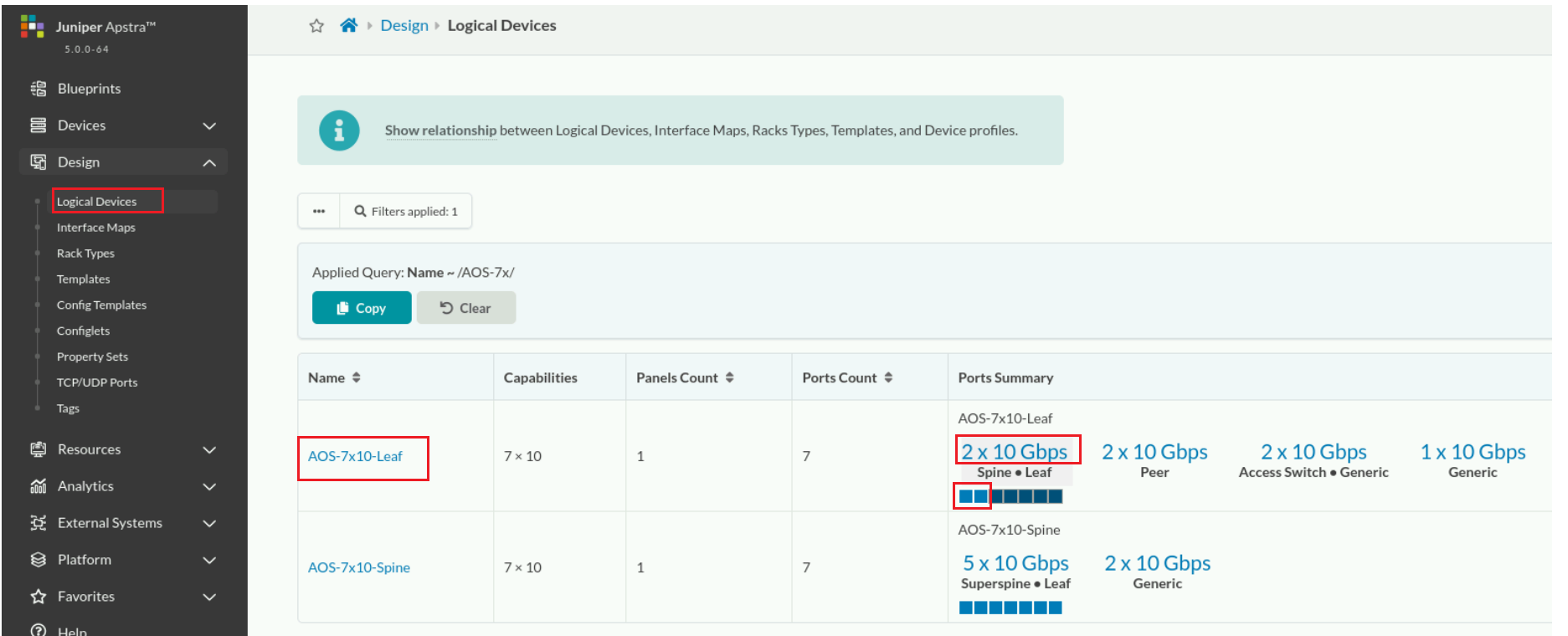
There are seven ports configured in the logical devices. At the time of IP fabric deployment, when this logical device is associated with an actual device, the actual device must have at least seven 10Gbps ports, but it can have more. Of the 12 ports, Apstra will configure only seven while the other five interfaces will just go unused.
The first port group contains two 10Gbps ports you can connect to either a spine or leaf node. Because this is the first port group in the list and it contains two ports, Apstra highlights the first two ports in the diagram.
Click the drop-down arrow next to the Interface map list to see the interface maps that this logical device is being used in.
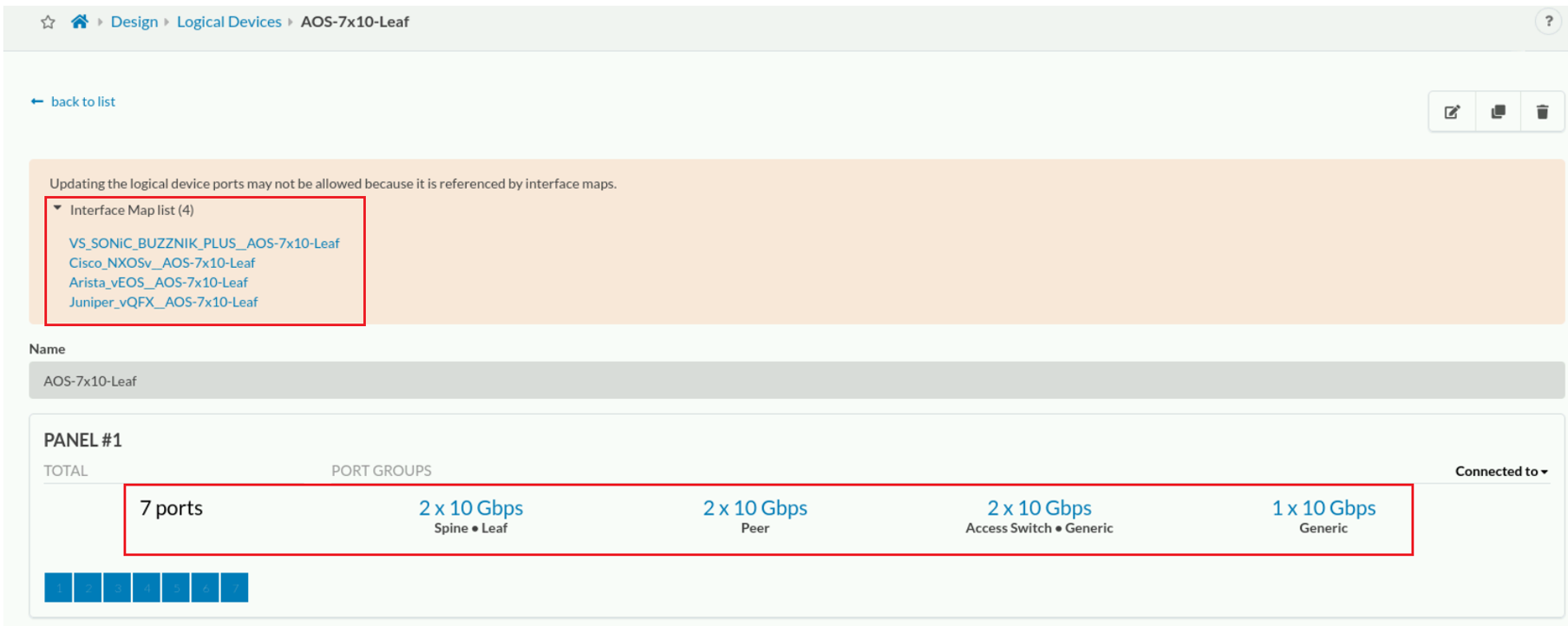
The pre-defined interface maps are named starting with a device profile followed by the logical device (an interface map's purpose is to associate a logical device with a device profile).
Navigate to Devices > Device Profiles and analyze the default list of officially supported devices.
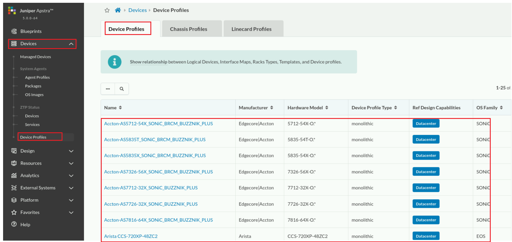
The name of the first device profile in the list is Accton-5712-54X_SONiC_BRCM_BUZZNIK_PLUS. The manufacturer of the first device in the list is Edgecore/Accton. This device profile enables the support of any Edgecore/Accton device that has a model number that starts with "5712-54X-O". The ".*" is part of the regular expression used to match on the hardware model. The entire regular expression is 5712-54X-O.*. This means that when Apstra first logs into the physical device and determines its hardware model, to be added to the list of managed devices, the model number must start with 5712-54X-O and then be followed by any number of digits. ".*" means "any number of digits".
The supported devices are non-modular (monolithic). The devices are expected to be running the SONiC software.
Click the name of the first device profile. Scroll to the Ports section of the device profile.
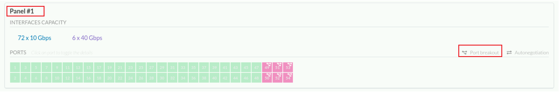
The diagram depicts what the interface panel looks like for any devices that match on this device profile. There are exactly 54 ports. The Interfaces Capacity section states that the profile supports seventy-two 10Gbps interfaces and six 40Gbps interfaces. To support these various interface types, you can configure each port for different speeds and also combine them with breakout cables.
Port breakout is also possible. That means that it is possible for a port breakout cable to be used so that a higher speed interface can be broken down into multiple lower-speed interfaces.
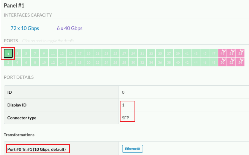
Select the first port of the ports diagram.
Click port 49 of the diagram.
You can configure port 49 for either four 10Gbps interfaces (using a breakout cable) or one 40Gbps interface. This will be a choice you make at the time you deploy your blueprint.
If you needed to manually configure port 49 as a 40Gbps interface, the interface name for that port is Ethernet48. If you needed to manually configure port 49 as four 10Gbps interfaces, the interface names for those ports areEthernet48 , Ethernet49 , Ethernet50, and Ethernet51 . This is important, so that Apstra knows the naming convention it should use when configuring the device

Comment
TABLE OF CONTENTS
- Navigating Apstra UI
- Configure : Logical Devices, Device Profiles, and Interface Maps
- Managing Devices
- Creating Resources and Tags
- Configuring Racks
- Configuring Templates
- Building and Deploying a Blueprint From a Template
- Working With The Active Blueprint
- Enabling Property Sets & Configlets
- Configuring Connectivity Templates
- Configuring Multitenancy
RECENT POSTS
- Installing Context-Aware Network Access Control using Cisco ISE Policies
- Designing Network Access Control that is Scalable using Cisco ISE Architecture
- Enterprise Network Access Control and Policy Enforcement using Cisco ISE
- Secure Device Administration and Network Access Using AAA Architecture
- Designing Enterprise-Class Hybrid Cloud Connectivity Using AWS Networking Services
- Exploring Core AWS Networking and Messaging Concepts for Modern Cloud Architectures
- Understanding Key AWS Services for Modern Cloud Architectures
- Building a Strong AWS Foundation with Amazon S3, EC2, and Virtual Private Cloud
- Understanding the ENSDWI Course: Advanced Cisco SD-WAN (Viptela) Concepts
- A Complete Guide to the DCACI-A Course: Mastering Advanced Cisco ACI Concepts


LEAVE A COMMENT
Please login here to comment.