EMAIL SUPPORT
dclessons@dclessons.comLOCATION
USExample 1: Route Inter-site Traffic through a Service
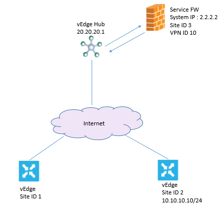
Consider below situation, where Site-1 has to send the traffic to site -2, but while sending to site-2, it has to route the traffic to Firewall service behind vEdge hub whose system IP is 20.20.20.1 and all are in same VPN.

On vEdge Hub router, configure Firewall service, once done OMP on this vEdge hub router will advertises one service route to vSmart Controller. This Service Route contains location of FW, TLOC of vEdge Hub router and service label of svc-id-1 which identify the service type of firewall.
vpn 10
service FW address 2.2.2.2
On vSmart controller, configure the control policy that redirect the data traffic from Site-1 to Site-2 through firewall. Once done vSmart controller will apply this policy to site-1.
policy
lists
site-list dclessons-firewall-sites
site-id 1
control-policy dclessons-firewall-service
sequence 10
match route
site-id 2
action accept
set service FW vpn 10
default-action accept
apply-policy
site-list dclessons-firewall-sites control-policy dclessons-firewall-service out
Here once match is done for Site-2 destination, accept the route and redirect it to firewall service provided by vEdge hub router located in VPN 10. For all non-matching traffic accept it if traffic is not for site-2. Apply this policy in outbound direction.
The TLOC is changed from Site-2 TLOC to vEdge Hub router TLOC. This TLOC is learned to vSmart controller from service route received by vEdge hub router.
The label is changed to svc-id-1 which identifies the firewall services. This label causes vEdge hub router to direct the traffic to firewall device.
Once the vEdge router receives the traffic, it forwards the traffic to IP 2.2.2.2 which is firewall system IP. Once Firewall process the traffic and return back to vEdge hub router, hub router then forwards it’s to final destination that is site-2.
Example 2: Route Inter-VPN Traffic through a Service Chain with One Service per Node.

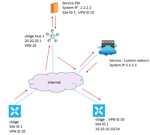
From above figure, it is required that from Site-1 VPN10 to destination Site-2 VPN 30 for destination subnet 10.10.10.0/24 to go to Firewall on vEdge Hub1 and then to custom service netsvc1 behind vEdge Hub 2 and then to final destination.


LEAVE A COMMENT
Please login here to comment.