EMAIL SUPPORT
dclessons@dclessons.comLOCATION
USACI Fabric Design
As we all know that ACI is a fully meshed fabric network, where every leaf is connected to every spine, which yields better throughput. This design is bested suited for single DC, but what if the enterprise has multiple DC sites.
In this case Enterprise face challenges that how Single Fully meshed fabric can be extended to multiple locations and still have same policies throughout
As ACI has matured, ACI are now able to provide connectivity between multiple Pods and even between multiple sites. There are following design option for interconnecting ACI fabrics.
- Single APIC Cluster/Single Domain
- Multiple APIC Cluster/Multiple Domain
Let’s discuss one by one both design and connectivity scenarios:
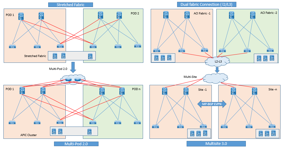
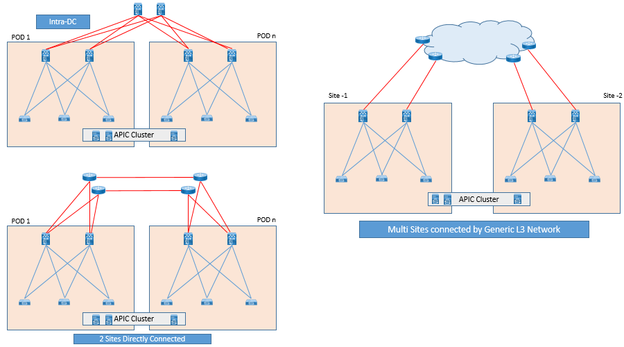
Single APIC Cluster/Single Domain: In ACI 1.0 ACI Stretched Fabric connectivity was introduced and which further enhanced to ACI multi-pod design in ACI 2.0 release. In both design leverage a single APIC cluster for policy definition and management for entire network.
It not only fulfill the requirement of making Active/Active data Centers by interconnecting them, but also allows to deploy application tiers with in single pod or across separate pods.
ACI multipod design provides extra enhancement, that it isolates the failure domains between pods. In Multipod design the Management plane is common for all pods, As soon as any configuration changes or policy definition is applied to APIC , its gets propagated to all pods managed by single APIC cluster.
There are some Pros and Cons of stretching Single Fabric design options, like you need to have dedicated leaf called a transit leaf (TL) at each site to provide path between sites. As to have redundancy, you should have two TL connected to other side of Spines. In this TL needs to be register to APIC and there is nothing to configure on TL.
The stretched fabric using TLs is a single ACI fabric design in which DC or sites are one Administrative domain (AD) in which any changes done on APIC Controller are applied to devices across DC or between Sites and one Availability Zone in which resources like Network, compute, Storage, are connected through high speed links to provide resiliency within Data Center in to multiple data halls.
For Site to Site Connectivity using TL includes dark fiber, DWDM Connectivity, EOMPLS Pseudo wire.
Dark Fiber:
ACI TL can be connected to spines using following QSPF Transceivers:
- Cisco QSFP -40G-LR4 ( 10 Km supported distance )
- Cisco QSFP -40GE-LR4 ( 10 Km supported distance )
- Cisco QSFP -40G-LR4L ( 2 Km supported distance )
- Cisco QSFP -40G-ER4 ( 40 Km supported distance )
Dense Wavelength-Division Multiplexing
By using DWDM, ACI fabric can be stretched up to a distance of 800Km with up to 10 msec latency between sites.
Ethernet over MPLS (EoMPLS) Pseudowire:
It Provide connectivity between leaf and Spine switches in stretched fabric when 40/100 Gbps long distance DWDM link between two sites are not available.
With the help of EoMPLS , two sites can be provided BW of 10Gbps, 40 Gbps, or 100 Gbps over distance of 800Km with up to 10 Msec latency between sites.
Multiple APIC Cluster/Multiple Domains: This type of design was first achieved by providing Dual-fabric connection via L2/L3 extension across ACI fabric as shown in above figure and later in ACI 3.0 it was further enhanced to ACI Multi-Site design.
In Multiple-Fabric Design, an independent APIC cluster is used and they manages each interconnected ACI fabric separately. In this Configuration & Policy definition is managed separately. This type of deployment is required in case of DR site, where Primary Site or DC got major failure and applications needs to be recovered.
These types of design ( left - Single Cluster , Right - Multiple APIC Cluster ) are mostly deployed when DC are in Active/Active fashion.
Stretched Fabric Failover Scenarios:
When a failure occurs at single inter-site Link, then there is no impact on ACI Operation. But it degrade the overall performance throughput between two sites. IS-IS Protocol within ACI fabric, reacts to link failure, and computes a new forwarding path based on topology change.
As long as there is a connectivity between sites, APIC cluster is maintained and controller nodes are synchronized.
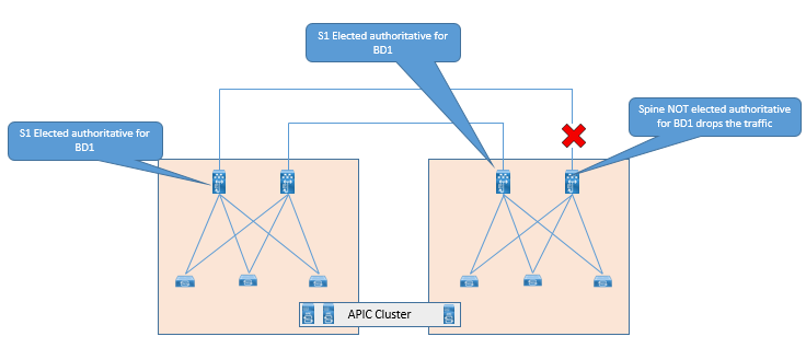
Now let’s suppose, all connections between sites are lost, the single fabric splits in to two fabrics and is referred as Spilt Brain.
In this scenarios, split fabric continue to operate separately and traffic forwarding is not affected at any point of time with in Site, but traffic forwarding may affect between sites.
Now Once New Endpoints are learned, Each Site Spine will get these endpoints details via COOP protocol, which sent from leaf to spine using ZeroMQ. The spines at each site will keep record of the newly learned End Points and will share within themselves with in sites.
In the case of Split brain , One site having two APIC cluster will maintain cluster Quorum , and hence has power to execute read and write operation to that site, while on other site , which has only one APIC controller , will be in minority state , due to which it will be a leader of any Database shards. In this case, APIC controller at site 2 will only have read only powers and it cannot make any configuration changes.
How Ever Site 2 fabric will still respond to network events such as workload migration, Link failure, node failure, and switch reload. When a Leaf switch learn any new Endpoint, it will send this information to Spine via COOP and also inform to APIC controller, so that administrator can view up-to-date endpoint information from single controller in DC Site2. When Link between two sites are lost, Leaf switches in DC 2 try to report the newly learned endpoints to shard leader (APIC resides on DC1) which is not reachable.
Now once the connection between sites are restored, New Endpoints learned are reported to Controller successfully and Spine proxy database for these two sites will merge to have identical proxy database mapping.
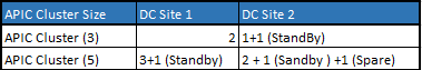
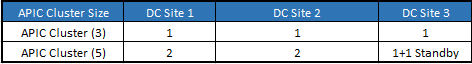
Below table shows best practice for deploying APIC controller at multiple sites (Scalable up to three APIC ) in Stretched fabric design that help prevent ACI fabric from being in minority state during single Site Failure Scenarios.
APIC Deployment in two-Site Stretch Fabric
APIC Deployment in three-Site Stretch Fabric
ACI Multi-Pod Overview
ACI Multi-Pod allow to interconnect separate ACI fabric and can be managed by centrally APIC cluster. Same APIC cluster is used to manage several pods and these APIC controller nodes can be deployed across different pods to form a single cluster. All interconnected pods function as a single ACI fabric.
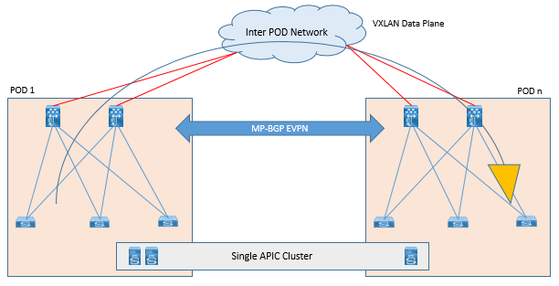
These different Pods are connected to each other via network called as Inter-Pod-Network (IPN) via Spine Nodes.
Following are the different Multi-pod supported typologies and connectivity options:
ACI Multi-Pod Scalability Options:
Following are the ACI Scalability Options in initial ACI 2.0 release.
- Maximum number of Pods: 4
- Max no of Leaf nodes across all pods: 300 (When 5 Node APIC Cluster)
- Max no of Leaf nodes across all pods: 80 (When 3 Nodes APIC Cluster)
- Max no of Leaf nodes per Pod: 200 (When 5 Node APIC Cluster)
- Max no of Spine nodes per Pod: 6
Following are the ACI Scalability Options in initial ACI 3.0 release.
Maximum number of Pods: 12
- Maximum number of Leafs nodes across all pods
- 400 With a 7-Node APIC cluster (From ACI Cluster Release 3.0)
- 300 With a 5 Node APIC Cluster
- 200 With a 4 Node APIC cluster (From ACI 4.0 Release)
- 80 With 3 node APIC Cluster
- Maximum No of leaf node per single pod: 200
- Maximum No of Spine Node per Single pod : 6
Spines & IPN Connectivity Options:
An IPN is a IP network, which connects to different ACI pods and allow communication between pods for east-west traffic flows.
In order to perform ACI Operations across Infrastructure, an IPN Must support, following specific functionalities like Multicast PIM Bidirectional (Bidir), DHCP Relay, OSPF, MTU, Dot1Q, and QOS.
Let see these design consideration one by one.
It is not necessary to connect each spine in Pod to IPN devices.
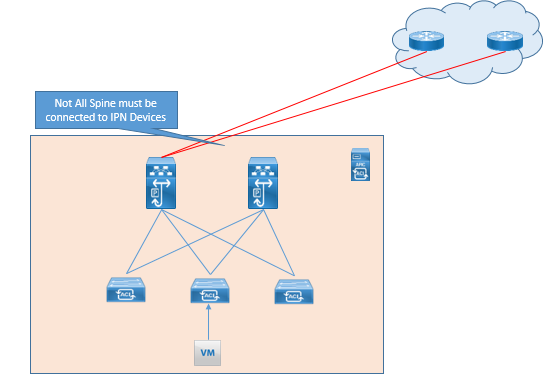
Direct Back to Back connection between spines in separate pods are not supported as shown in below figure.
Multicast Support:
As we know, same EPG/BG is stretched between multiple Pods, Same multicast group associated to BD needs to be extended across IPN using PIM-Bidir. For this IPN devices must support IP range of at least /15. Below points explain why PIM Bidir is needed:
Using PIM Bidir, a single (*.G) entry is created for given BD. Using this the routing table of each leaf will not increase exponentially as ACI fabric Grows.
(*, G) entry is created, in IPN as soon as BD is activated, and extended in ACI multi-Pod fabric. Now when the BUM traffic arises, then network is ready to perform and send these BUM traffic, avoiding longer convergence time for application.
Cisco also recommends PIM Bidir in an IPN based on regression testing & filed Experience.
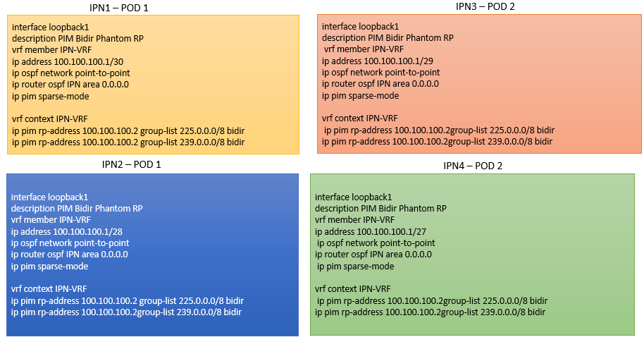
Now while deploying PIM Bidir, we require a more efficient RP, for which we use an efficient RP redundancy method in PIM Bidir called as phantom BD. In this a single RP will handle all multicast flows and if this RP goes down, another RP takes over. This method can be achieved by configuring different subnet mask on loopback interface addresses for each IPN router.
See below topology for ACI multicast IPN RP Configuration:
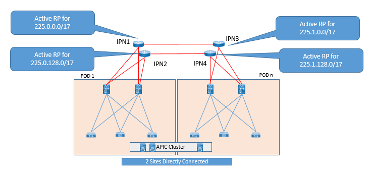
Lets see below example configuration:
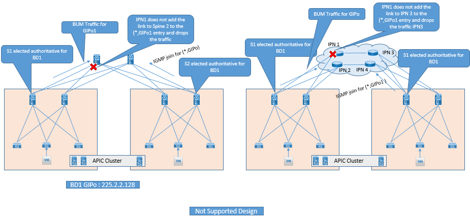
Below are non-Suitable design for Multicast support.
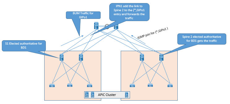
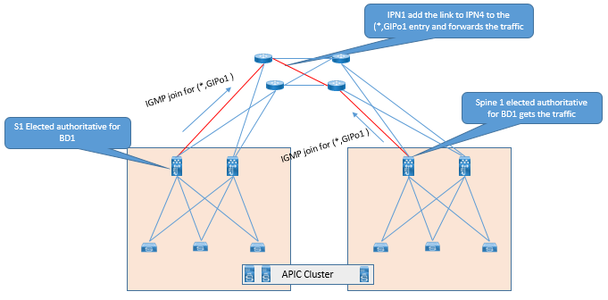
Below are some suitable connectivity options which can be used for connectivity between Spine and IPN device.
DHCP Relay Support.
When a New Leaf or Spine is provisioned in a Pod, which are physically separated by IPN, then in this case how these newly provisioned Leaf or Spine will get IP. In order to solve this problem, DHCP relay needs to be enabled in the IPN, so that IPN forwards the DHCP handshake traffic between APIC and newly provisioned Leaf and Spine.
When a new spine or leaf in a new pod is powered up, it sends the DHCP request located to APIC at Pod 1. This DHCP request is then relayed by IPN router to spine in Pod 1 and finally it reaches to APIC controller resides in Pod1.
Now when DHCP Process is completed, Spine or Leaf will gets it configuration from APIC and hence will join the fabric.

TABLE OF CONTENTS
- ACI Initial Fabric Configuration
- ACI Configure Tenant VRF & Bridge Domain
- ACI Configure Filters and Contracts
- ACI Configure Three-Tier Application Profile
- ACI Configure Baseline Interface Policies
- ACI Integration with VMWARE
- ACI Inter Tenant Connectivity
- ACI Extend Bridge Domain by External Layer 2 Connection
- ACI External Network Connectivity to External Switch via Trunk
- ACI Static Routing for External Layer 3 Connectivity
- ACI OSPF Routing for External Layer 3 Connectivity
- ACI EIGRP Routing for External Layer 3 Connectivity
- ACI EBGP Routing for External Layer 3 Connectivity
- IPN Configuration
- ACI Multipod Overview
- ACI Multi-Pod Building Control Plane
- ACI Multi-Pod Data Traffic Flow
- Multi-Pod Connectivity via External L3
- Host Tracking Subnet Check & Limit IP Learning
- Service Graph Introduction
- BD VRF & EPG Design consideration – Service Chaining
- IP Routing & VRF Design Consideration – Service Chaining
- L3Out for Routing to L4-L7 Devices
- Routed Mode ( Go-To mode ) for L4-L7 Appliance
- Transparent & One ARM mode for L4-L7 Appliance
- Policy Based Redirect in ACI
RECENT POSTS
- Which AWS Advanced Networking Labs Course Includes # Real World Traffic Flows and Examine Objectives?
- How Do You Practice Cisco Nexus Configuration with Online Labs No Physical Equipment?
- Why Cisco SD-WAN Viptela Training is Necessary in the Current Cloud-First Networking Age
- 5 Best Reasons to Learn Cisco SD-Access: From Networking Issues to Automation Solutions
- What is Cisco SD-LAN? A Beginner’s Guide to Software-Defined Access
- Why Enroll in Cisco UCS Online Training? Key Benefits for Network Engineers
- Why Python Network Automation Training is a Must-Have for Modern IT Engineers
- What to Expect from the Best Docker Training Courses: Features That Matter
- Why are Advanced Cisco ACI skills essential for Modern Data Center Engineers
- Transform Your Career: The Skills You Gain from AWS Solution Architect Associate Training


LEAVE A COMMENT
Please login here to comment.