EMAIL SUPPORT
dclessons@dclessons.comLOCATION
USSDA Extension to IOT
Cisco DNA Center automates deployment of campus fabric that can also be extended to IOT devices. IOT switches can also be made part of fabric, and those switches can be managed and monitored by DNA Center. These IOT switches are also called as Extended Nodes.
An Extended node connects to Campus SD-Access Fabric as Layer 2 mode, which connect the IOT endpoints, and does not support fabric technology. With the help of DNA center, extended node can be on boarded from factory reset state using PnP method, enabling security controls on the extended network and enforcing fabric policies to endpoints connecting to extended nodes.
Types of Extended Node
Thera are two type of extended nodes. , Lets discuss one by one.
Extended Nodes
Extended nodes is layer 2 switch that connects to Fabric Edge, and performs 802.1X or MAB authentication with NAC server. With ISE Dynamic VLAN assignment can be done on extended nodes, whereas SGT’s cannot be assigned to extended node client port even if ISE pushes the SGT.
End devices connected to an extended node are placed in an SGT based on their VLAN, and Cisco DNA Center is used to configure the static VLAN-to-SGT mapping on the fabric edge. The fabric edge performs Location Identifier Separation Protocol (LISP), Virtual Extensible LAN (VXLAN), and Scalable Group Access Control List (SGACL) enforcement for the clients connecting to the extended nodes.
By DNA Center, following activity can be done for extended nodes.
- Onboarding of Extended node
- Orchestration of AAA Configuration
- SGT-VLAN Mapping
- Multicast Configuration on connected port.
Policy Extended Nodes
Following are the capabilities of Policy Extended Nodes
- Performs the 802.1X/MAB authentication
- Dynamically apply VLAN and SGT attributes to end points
- Performs SGACL enforcement
- Inline tagging of SGT between fabric edge and Policy Extended node by DNA
- Hardware and Software versions needs to be compatible for extended node to act as Policy Extended node.
An Extended node can be connected to Edge switch via Trunk port or via Port-channel protocol. If an enterprise has different OT environment like OT switches forms a Ring type topology and running REP protocol ( Resilient Ethernet Protocol ) for faster convergence, resiliency and High Availiblity.
Below are some Topology options using REP protocols in SD-Access deployment
- Extended node ring to StackWise Virtual (SVL) fabric edge. REP edge on the fabric edge. Two ways out of extended node ring. No single point of failure.
- Extended node ring to stacked fabric edge. Two ways out of extended node ring. Stacked fabric edge might cause a potential single point of failure.
- Extended node open ring to SVL fabric edge.
- Extended node open ring to stacked fabric edge.
- Single extended node ring to dual-homed stacked fabric edge.
Extended Node Configuration
DNA Center automates onboarding and configuration of extended nodes so that fabric policies can be applied to IOT networks.
Operator must refer Cisco SD-Access Product Compatibility Matrix to select which hardware is suitable for extended nodes. Now we will see how extended nodes are on boarded assuming that Cisco SD-Access fabric is already provisioned.
Step1: Provide CLI credential and SNMP setting to site level on DNA Center, where extended node is to be provisioned.
Step2: Provide IP address pool for extended nodes. DNA uses PnP method for which DNA center will configure Loopback interface for discovered extended node.
Step3: Configure IOT pool for IOT endpoints, Reserve the IP pool at site level.
Step4: Create a Virtual Network VN for IOT devices, to provide traffic isolation if necessary. You can also leverage SGTs to apply segmentation policies if IOT devices are in same VN as campus users.
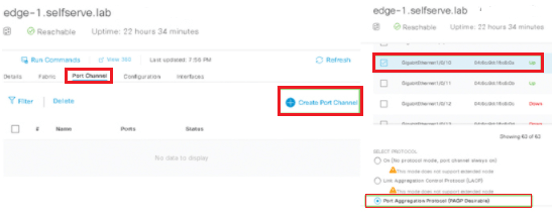
Step 5: (Optional) Configure port-channel on fabric edge node to connect to extended node. If No authentication mode is selected, Port-Channel is created automatically. If you are using IE3300/3400 rugged series switches, port-channel should be in static mode.
Use below figure to create Port-channel using PAgP.
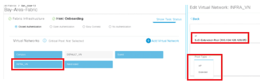
Step 6: Assign the extended node management IP address pool, Fabric | Host Onboarding tab, scroll to the Virtual Networks section, click INFRA_VN, click Pool Type, and choose Extended. This step results in an SVI creation of the IP pool. The SVI is placed in the INFRA_VN.
Below is IP Pool configuration pushed by DNA center
FE2-9300-04# sh run int Vlan1024 interface Vlan112 description Configured from Cisco DNA-Center mac-address 0000.0c9f.f45f ip address 10.12.12.129 255.255.255.128 ip helper-address 10.10.13.12 no ip redirects ip route-cache same-interface no lisp mobility liveness test lisp mobility 10_12_12_128_INFRA_VN_IPV4 end
Step7: On Host Onboarding tab, Select port-channel and assign it as an extended node
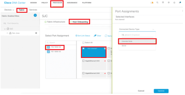
Once above configuration is done, Configuration is pushed on fabric edge with port-channel creation and assignment of extended node.
FE2-9300-04# sh run int gig 1/0/2 interface GigabitEthernet1/0/2 switchport mode trunk channel-group 1 mode desirable end FE2-9300-04# sh run int port-channel 1 interface Port-channel1 switchport mode trunk end
With the Help of PnP method, External nodes are discovered and are added to inventory. , site and fabric topology.
Onboarding Extended Node

Comment
TABLE OF CONTENTS
- How to add Site, Floor & Building
- How to Create Wireless Network Profile
- How to Provision a Device to New Site
- How to do ZTP via PnP of New Device
- How to Configure Multi-Site Remote Border
- How to Configure Fabric In Box Configuration
- How to Perform SWIM Action
- How to Configure Device RMA
- How to Create Virtual Network
- How to Create Group Based Access Control Policies
- How to Create Access Contract
- How to work on Policy Analytics
- How to do AI Endpoint Analytics
- Learn Overall Health of Network Devices & Health Score
- Learn how to visualize the Over all health of Wireless Client
- Learn how to Application Analysis via DNA
- How to analyse the Sensors Performance Testing
- Management of Industrial Extended Network
- How to Configure Security for IOT
- How to Create Template for IOT Network
- How to Create Network Profile
RECENT POSTS
- Installing Context-Aware Network Access Control using Cisco ISE Policies
- Designing Network Access Control that is Scalable using Cisco ISE Architecture
- Enterprise Network Access Control and Policy Enforcement using Cisco ISE
- Secure Device Administration and Network Access Using AAA Architecture
- Designing Enterprise-Class Hybrid Cloud Connectivity Using AWS Networking Services
- Exploring Core AWS Networking and Messaging Concepts for Modern Cloud Architectures
- Understanding Key AWS Services for Modern Cloud Architectures
- Building a Strong AWS Foundation with Amazon S3, EC2, and Virtual Private Cloud
- Understanding the ENSDWI Course: Advanced Cisco SD-WAN (Viptela) Concepts
- A Complete Guide to the DCACI-A Course: Mastering Advanced Cisco ACI Concepts


LEAVE A COMMENT
Please login here to comment.