EMAIL SUPPORT
dclessons@dclessons.comLOCATION
USVirtual Network
The foundation for the overlay networks created by Juniper Apstra software is the Virtual Extensible LAN (VXLAN) protocol.
Hardware VTEP Functionality
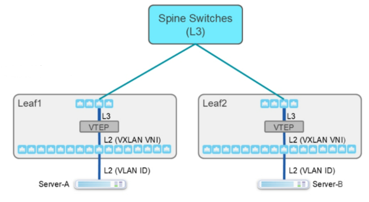
A hardware VXLAN tunnel endpoint (VTEP, the leaf nodes in the diagram) is a device in the network that takes Ethernet frames (from the servers in the diagram) and encapsulates those frames inside VXLAN IP packets.
As an example, imagine Server-A and Server-B in the same Ethernet broadcast domain. As you can see, there is a problem. You have attached Server-A and Server-B to two different switches and a Layer 3 (L3) network exists between them (we have enabled routing only between the leaf and spine nodes).
How can we keep the underlay network intact (the underlay is the L3 network between leaf and spine nodes) but be able to have Server-A and Server-B communicate as if they were on the same Layer 2 (L2) broadcast domain? One answer is creating an overlay network. We can tunnel (encapsulate) the L2 Ethernet frames inside IP packets as they traverse the overlay network. VXLAN is the IP tunneling/encapsulation method used by Juniper Apstra.
VXLAN Data Plane
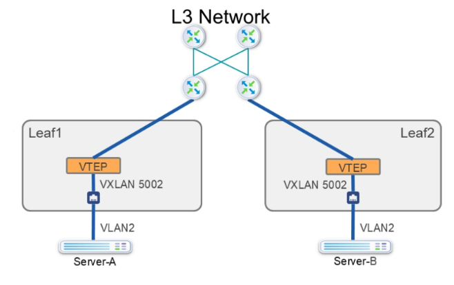
Continuing with our example from the previous figure , let us walk an Ethernet frame from Server-A to Server-B:
- Server-A sends an Ethernet frame with a destination media access control (MAC) address of Server-B.
- Leaf1, a hardware VTEP, receives an Ethernet frame on an interface that you have configured to map the incoming Ethernet segment (either tagged or untagged, it does not matter) into a VXLAN tunnel. A VXLAN tunnel is differentiated by its destination IP address (the Leaf2 switch's loopback address) and a VXLAN network identifier (VNI).
- Leaf1 performs a MAC table lookup. From the MAC table lookup, it determines that it must forward the Ethernet frame over the VXLAN tunnel to Leaf2, so it encapsulates the Ethernet frame in a VXLAN IP packet.
- Leaf1 and the routers along the way forward the IP packet over the underlay network (which routes the now IP packet) until it reaches its destination, Leaf2's loopback address.
- Leaf2, upon receiving the VXLAN packet, notices that the destination address of the packet is Leaf2’s loopback interface and that it is a VXLAN packet. Leaf2 de-encapsulates the VXLAN packet, leaving only the original Ethernet frame to be forwarded. Leaf2 uses the VNI of the received VXLAN packet to determine which MAC table should forward the resulting Ethernet frame (there may be several MAC tables depending on the number of tenants).
- Leaf2 performs a MAC table lookup on the MAC table associated with the interface-facing Server-B and then forwards the Ethernet frame towards Server-B.
- Server-B receives the original Ethernet frame that was sent by Server-A as if the two servers were in the same broadcast domain.
 Juniper Apstra Multitenancy Model
The below figure shows the multitenancy model used by Juniper Apstra. So far, we have discussed using VXLAN to enable devices to be separated by a routed network to communicate as if we attached them to the same Ethernet segment. How does Juniper Apstra handle the scenario when devices on two different VXLAN overlay networks must communicate? Juniper Apstra uses the model on the slide to offer this functionality.
We describe the model as follows:
Tenant — A tenant is just one of potentially numerous customers that you, as the administrator, host in your data center. Each tenant relies on you, as the administrator, to ensure that other tenants cannot access the resources attached to their overlay networks.

Comment
TABLE OF CONTENTS
- Navigating Apstra UI
- Configure : Logical Devices, Device Profiles, and Interface Maps
- Managing Devices
- Creating Resources and Tags
- Configuring Racks
- Configuring Templates
- Building and Deploying a Blueprint From a Template
- Working With The Active Blueprint
- Enabling Property Sets & Configlets
- Configuring Connectivity Templates
- Configuring Multitenancy
RECENT POSTS
- Understanding Cisco ISE Authentication and Authorization Policies
- Installing Context-Aware Network Access Control using Cisco ISE Policies
- Designing Network Access Control that is Scalable using Cisco ISE Architecture
- Enterprise Network Access Control and Policy Enforcement using Cisco ISE
- Secure Device Administration and Network Access Using AAA Architecture
- Designing Enterprise-Class Hybrid Cloud Connectivity Using AWS Networking Services
- Exploring Core AWS Networking and Messaging Concepts for Modern Cloud Architectures
- Understanding Key AWS Services for Modern Cloud Architectures
- Building a Strong AWS Foundation with Amazon S3, EC2, and Virtual Private Cloud
- Understanding the ENSDWI Course: Advanced Cisco SD-WAN (Viptela) Concepts


LEAVE A COMMENT
Please login here to comment.