EMAIL SUPPORT
dclessons@dclessons.comLOCATION
USBuild & Deploy Blueprint
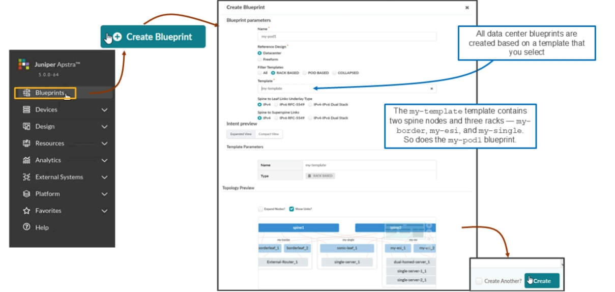
Creating a blueprint is a simple task. Click Create Blueprint, assign your blueprint a name, and select a template that will be the basis for your blueprint.
Global Blueprint Dashboard
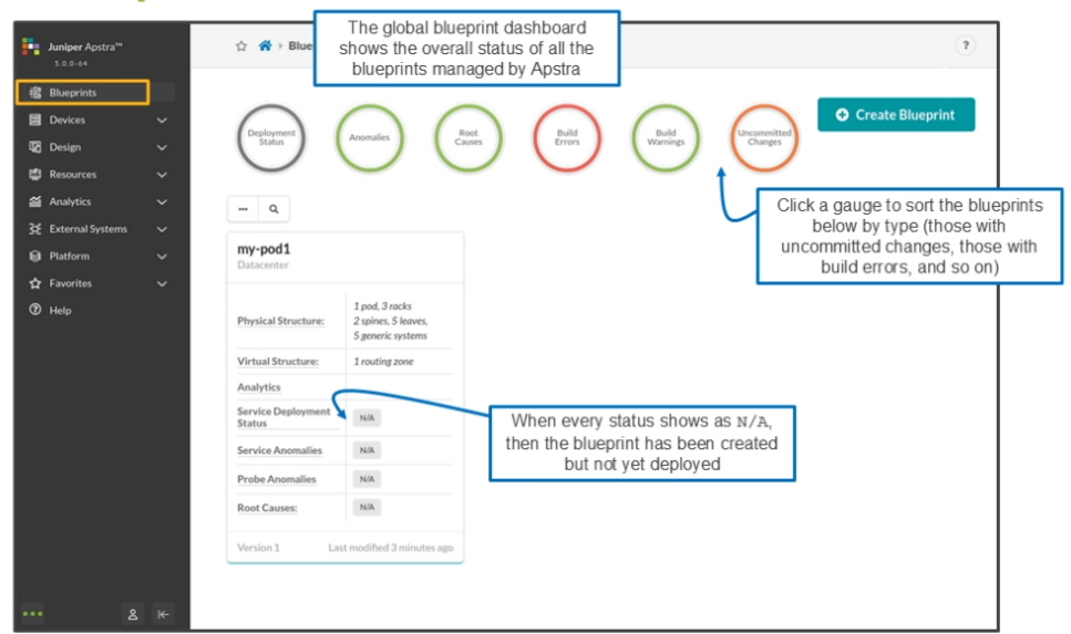
When you select Blueprints from the navigation pane on the left side of the UI window, Apstra takes you to the global blueprint dashboard. Below the gauges at the top of the page, you will find panels that represent each of the blueprints that this Apstra server is currently managing.
Here, there is only one blueprint that this server is currently managing, but there could be many. The gauges at the top enable you to sort the blueprints by their status. For example, if you click the gauge labeled Uncommitted Changes , Apstra will only display the panels for blueprints that have uncommitted changes
After you click Create on the previous section, Apstra scaffolds a blueprint for you (if you watch closely, the UI displays the message like "Scaffolding the blueprint"). It will create the skeleton bones of a blueprint for you. Your job at that moment is to complete the build workflow. After completing the build workflow, you should have a fully operational blueprint (running IP fabric).
Satisfying the Red Indicators
In the scaffolded blueprint, Apstra helps you through the build workflow using the red indicators. The goal of the workflow is to turn the red indicator on the Staged tab to green, which causes the red indicator on the Uncommitted tab to turn yellow. It is at that moment that we perform the Commit operation, which pushes the underlay and overlay routing configuration to the devices.
If you analyze the red indicators, the Staged tab has a red indicator because its Physical tab has a red indicator. The Physical tab has a red indicator because its Build tab has a red indicator. The Build tab has a red indicator because its Resources and Device Profiles tabs have red indicators. One of the Build tab's tabs has a yellow indicator. The tab with the yellow indicator is the Devices tab.
Yellow indicators show you may need to look at that tab as well. Finally, you can see that we have selected the Resources tab. The Resources tab has a red indicator because we have not chosen resources for autonomous system (AS) numbers, loopback addresses for spine nodes and leaf nodes, or IP addressing for spine-to-leaf links. To change the indicator for any tab from red to green, all the indicators that fall within that tab must be green. Sometimes a yellow indicator within a tab will permit that containing tab to turn green too.
Since the goal is to turn the indicator for the Staged tab from red to green, you must start at the very bottom. You must start in the Build tab.
Assigning Resources
The build tab has four tabs — Resources , Device Profiles , Devices, and Configlets . The correct workflow to turn the indicator for Build tab from red to green is to satisfy the Resource tab, the Device Profiles tab, and the Devices tab in that order. Since the Configlets tab is already green, there is nothing to satisfy on that tab.
Remember that we created resources at the global level of the UI (the Resources option on the menu on the left side of the UI). To assign resources in the blueprint, you must have already created the global resources. As you can see on the figure, Apstra shows that it needs two AS numbers to assign to the spine nodes in the blueprint. You must inform Apstra from which ASN pool that it should reserve the AS numbers.
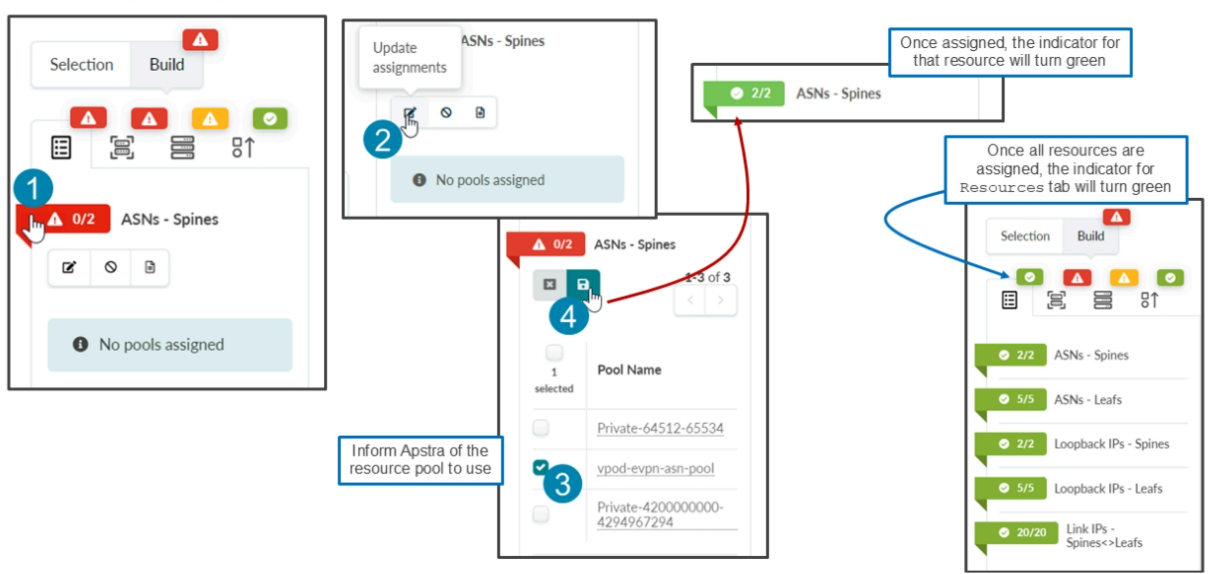
The figure shows the steps to set the resource to be used by Apstra. You must perform similar steps for the remaining resource requirements. Notice that after assigning resources to the blueprint, all the indicators under the Resources tab have turned green, which causes the indicator for the Resources tab to turn green as well. At that point, you can move on to the Device Profiles tab.
Assigning Interface Maps
The Device Profiles tab implies we will work with device profiles and yet what we can select is only an interface map. As mentioned earlier the moment you associate an interface map with a logical device, Apstra realizes the required device profile to be used.
Notice that Apstra requires you to assign seven interface maps to the seven logical devices that represent the nodes of your blueprint.
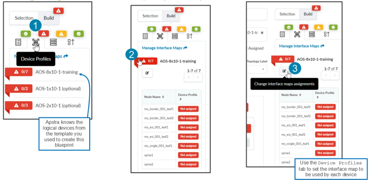
Notice that the Update interface map for AOS-8x10-training is initially mostly empty. It shows all of the nodes but it has no entries for their interface maps or device profiles.
Use the drop-down menu to select an interface map for each of the nodes. The device profile automatically gets populated based on the interface map you select. The moment you click Update Assignments, each of the devices in your blueprint is required to match the device profile that you just set here. They cannot be Juniper QFX5120s or QFX10008s, they must be Juniper vEXs or SONiC virtual switches.

Comment
TABLE OF CONTENTS
- Navigating Apstra UI
- Configure : Logical Devices, Device Profiles, and Interface Maps
- Managing Devices
- Creating Resources and Tags
- Configuring Racks
- Configuring Templates
- Building and Deploying a Blueprint From a Template
- Working With The Active Blueprint
- Enabling Property Sets & Configlets
- Configuring Connectivity Templates
- Configuring Multitenancy
RECENT POSTS
- Understanding Cisco ISE Authentication and Authorization Policies
- Installing Context-Aware Network Access Control using Cisco ISE Policies
- Designing Network Access Control that is Scalable using Cisco ISE Architecture
- Enterprise Network Access Control and Policy Enforcement using Cisco ISE
- Secure Device Administration and Network Access Using AAA Architecture
- Designing Enterprise-Class Hybrid Cloud Connectivity Using AWS Networking Services
- Exploring Core AWS Networking and Messaging Concepts for Modern Cloud Architectures
- Understanding Key AWS Services for Modern Cloud Architectures
- Building a Strong AWS Foundation with Amazon S3, EC2, and Virtual Private Cloud
- Understanding the ENSDWI Course: Advanced Cisco SD-WAN (Viptela) Concepts


LEAVE A COMMENT
Please login here to comment.