EMAIL SUPPORT
dclessons@dclessons.comLOCATION
USConnectivity Templates
Connectivity templates are necessary when you must add devices other than a superspine, spine, leaf, or access devices. Juniper Apstra software refers to these types of non-fabric devices as generic systems. The most common generic systems are servers, routers, or firewalls that you want to attach to IP fabric nodes. With generic systems, the door is open for you to define the connectivity for any non-fabric device in just about any way that you seek.
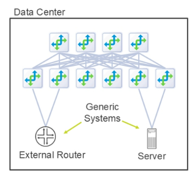
Generic Systems
You can add generic systems to racks during the design process, but just instantiating a blueprint containing that rack does not by itself enable a generic system to forward traffic to any destination. After we instantiate a blueprint, we will use connectivity templates to enable the ability for a generic system to send and receive traffic.
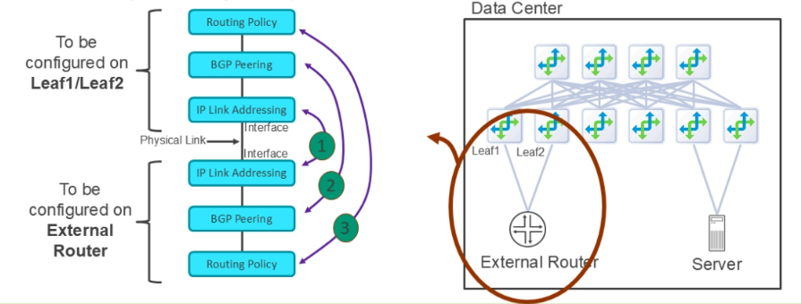
Before we discuss connectivity templates, let’s discuss what would be necessary if you needed to manually add an external router to the fabric. The figure shows that the configuration on Leaf1 (for example) and the external router happens in three steps:
- IP link addressing — With the physical link in place between the interfaces of the leaf and external router, you must configure the IP addresses on both devices. You must coordinate the IP addressing such that the host addresses are on the same subnet.
- BGP Peering — With the IP addressing in place, you must then configure the BGP peering on both devices. You might need to peer between loopback addresses, which would cause you to add a static route to the remote device's loopback interface. You must coordinate the BGP peering settings like local source address, local autonomous system (AS), remote address, remote AS, and internal or external BGP.
- Routing policy — With BGP peering in place, you must configure the BGP export and import policies on both devices to determine which routes each device will advertise and receive, respectively.
Routing Policies
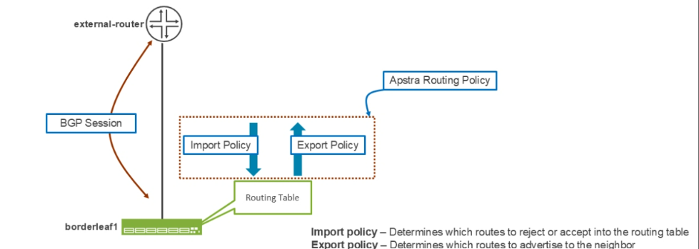
When enabling BGP between a leaf node and a generic system, you must apply a routing policy to the BGP neighbor. If you were to configure this manually on a Junos device, you must configure both an import and an export policy.
An export policy defines the routes a router will redistribute from its routing table (also known as routing information base [RIB]) toward the BGP neighbor. An import policy defines which of the routes that a router receives from its BGP peer will it permit to be added to its routing table. In Apstra terms, routing policy is a combination of both import and export policies combined into one.
To create or view Apstra routing policies, you can go in your blueprint to Staged (or Active) > Policies > Routing Policies . The settings that are enabled on the default policy called Default_immutable, the settings are:
Import policy — The settings are Default (accept 0/0 and those listed in Extra import routes ), All Routes (accept all routes), or Extra Only (accept only routes listed in Extra import routes ).
Extra import routes — Set a list of specific routes that a node will accept into the routing table.
Spine Leaf Links — Advertise the spine-to-leaf links.
L3 Edge Server Links — If you have connected an IP fabric node to a generic system (a common interface between them, not over a Virtual Extensible LAN [VXLAN] tunnel) and they belong to the same IP subnet, then the node advertises that subnet to BGP neighbors.
L2 Edge Subnets — If an IP fabric node belongs to the same IP subnet as a generic system over the combination of a VXLAN tunnel and an switch virtual interface (SVI) interface, then that node advertises that subnet to BGP neighbors.
Static Routes — An IP fabric device advertises all of its static routes to BGP neighbors.
Extra export routes — Set a list of additional routes that an IP fabric device will redistribute from the routing table.
Aggregate Prefixes — You cannot apply a policy with this setting in a connectivity template. A policy with this setting can only apply to a routing zone. When configured, Apstra adds an aggregate route (similar to a static route with a null/reject next hop) to the VPN route and forwarding table (VRF). The IP fabric node not only advertises the aggregate route but also suppresses the advertisement of the contributing routes (routes that fall within the scope of the aggregate route).
Expect Default IPv4 Route — If you have configured a BGP session using IPv4 address family identifier (AFI), set the yes setting for Expect Default IPv4 Route for that session. If the IP fabric device receives no IPv4 default route from the generic system, then Apstra raises an anomaly.
Expect Default IPv6 Route — If you have configured a BGP session using IPv6 AFI, set the yes setting for Expect Default IPv6 Route for that session. If the IP fabric device receives no IPv6 default route from the generic system, then Apstra raises an anomaly.
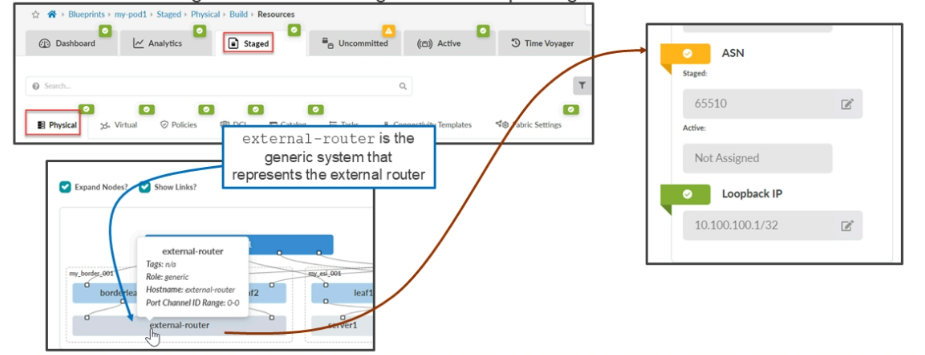
Generic System Settings
Before creating your connectivity template, it makes sense to enter some settings for the generic device that represents the external router. In particular, set the AS number and loopback IP address of the external router as shown on the below figure. This gives Juniper Apstra the information it needs to configure its static routing and BGP peering on the leaf nodes, where necessary.
Adding A New Connectivity Template
In your blueprint, navigate to Staged > Connectivity Templates to add a new template.
Initially, Apstra places you in the Parameters tab where you configure a name for your template. Currently, there are not too many parameters to set on this tab, but this will change. After a few sections, we will return to the Parameters tab to configure some settings for our template.
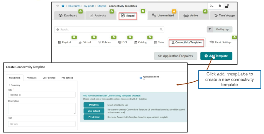
To build a connectivity template, you have a few choices. You can go to the Pre-defined tab and choose a pre-defined template to use. You can go to the User-defined tab and choose a template that was created by you or your fellow network engineers. Finally, you can go to the Primitives tab and create an entirely new template using the primitives that are provided by Juniper Apstra.
When creating a connectivity template, notice the diagram that sits on the right side of the window. Much like building a rack, the diagram changes as you add primitives to the template. Also, notice that every diagram will have a set of blue dots and green dots. The blue dots represent application points or the place where you can attach additional primitives.

Comment
TABLE OF CONTENTS
- Navigating Apstra UI
- Configure : Logical Devices, Device Profiles, and Interface Maps
- Managing Devices
- Creating Resources and Tags
- Configuring Racks
- Configuring Templates
- Building and Deploying a Blueprint From a Template
- Working With The Active Blueprint
- Enabling Property Sets & Configlets
- Configuring Connectivity Templates
- Configuring Multitenancy
RECENT POSTS
- Understanding Cisco ISE Authentication and Authorization Policies
- Installing Context-Aware Network Access Control using Cisco ISE Policies
- Designing Network Access Control that is Scalable using Cisco ISE Architecture
- Enterprise Network Access Control and Policy Enforcement using Cisco ISE
- Secure Device Administration and Network Access Using AAA Architecture
- Designing Enterprise-Class Hybrid Cloud Connectivity Using AWS Networking Services
- Exploring Core AWS Networking and Messaging Concepts for Modern Cloud Architectures
- Understanding Key AWS Services for Modern Cloud Architectures
- Building a Strong AWS Foundation with Amazon S3, EC2, and Virtual Private Cloud
- Understanding the ENSDWI Course: Advanced Cisco SD-WAN (Viptela) Concepts


LEAVE A COMMENT
Please login here to comment.