EMAIL SUPPORT
dclessons@dclessons.comLOCATION
USCisco SD-Access Underlay Methods
There are two methods of designing the SD-Access Underlay. Let’s discuss one by one.
Manual Underlay
In this Underlay need to be designed completely with Layer 3 Links to avoid Layer 2 issue and you can use any Routing Protocol like OSPF, ISIS or EIGRP. The link between devices needs to be configured as Point to Point interface with /30 or /31 and routing protocol should use load-balancing mechanism like ECMP.
In this, it is very much necessary to advertise each fabric node /32 loopback interface explicitly via routing protocol, because these address are used in destination field of each fabric packet header.
BFD and aggressive timers are also used to decrease failover and convergence timers.
Below example shows that ISIS is used as Routing protocol and BFD is enabled on interface of each devices.
Interface Loopback0 Description Fabric Underlay RID - do not change ip address 10.12.0.1 255.255.255.255 ip router isis ! Interface GigabitEthernet1/0/10 description To Border-2 te1/0/10 no switchport ip address 10.12.1.33 255.255.255.252 ! ip router isis bfd interval 300 min_rx 300 multiplier 3 no bfd echo ! interface GigabitEthernet1/0/11 description To edge1 te1/0/2 no switchport ip address 100.12.2.1 255.255.255.252 ip router isis bfd interval 300 min_rx 300 multiplier 3 no bfd echo ! router isis net 49.0000.0011.0111.0010.00 is-type level-2-only router-id Loopback0 domain-password cisco metric-style transition log-adjacency-changes bfd all-interfaces !
Automated LAN Underlay
With the help of DNA Center, an Operator can use automated workflow called LAN automation, which helps in building SD-Access underlay in Greenfields environment. When new device is added to network, LAN automation automatically onboard and configure it and make it part of company SD-Access fabric overlay.
LAN Automation automatically upgrades software on the switch to match company “Golden Image “version if required. Once device is on boarded switch can be fully managed and configured from DNA Center.
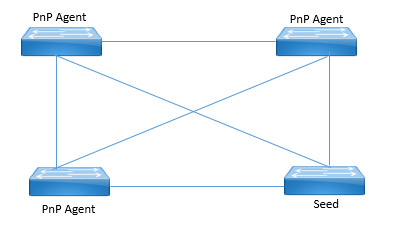
LAN automation required an existing configured device in fabric, used as seed device as the basis for device discovery and automatic configuration. This seed device does not need to be part of fabric already. Only requirement is that this seed device should be reachable to DNA Center and already discovered and on DNA Center Inventory. After that DNA Center uses the PnP Agent (enabled by default) to start the process for each new device.
Below is the LAN automation topology which has one seed device and three new switches to be on boarded.
LAN Automation requires following fields to be completed before starting the process.
- Primary Device: As seed device
- Peer Device (Optional): A second existing device to get more accurate view of network topology.
- Primary Device Ports: Interfaces over all other new device are connected.
- Discovered Device Site: The site that newly discovered devices are assigned to after discovery.
- IP Pool: IP POOL for /31 and /32 loopback interfaces on each new device. This IP pool configured must have at least /25 network mask.

Comment
TABLE OF CONTENTS
- How to add Site, Floor & Building
- How to Create Wireless Network Profile
- How to Provision a Device to New Site
- How to do ZTP via PnP of New Device
- How to Configure Multi-Site Remote Border
- How to Configure Fabric In Box Configuration
- How to Perform SWIM Action
- How to Configure Device RMA
- How to Create Virtual Network
- How to Create Group Based Access Control Policies
- How to Create Access Contract
- How to work on Policy Analytics
- How to do AI Endpoint Analytics
- Learn Overall Health of Network Devices & Health Score
- Learn how to visualize the Over all health of Wireless Client
- Learn how to Application Analysis via DNA
- How to analyse the Sensors Performance Testing
- Management of Industrial Extended Network
- How to Configure Security for IOT
- How to Create Template for IOT Network
- How to Create Network Profile
RECENT POSTS
- Installing Context-Aware Network Access Control using Cisco ISE Policies
- Designing Network Access Control that is Scalable using Cisco ISE Architecture
- Enterprise Network Access Control and Policy Enforcement using Cisco ISE
- Secure Device Administration and Network Access Using AAA Architecture
- Designing Enterprise-Class Hybrid Cloud Connectivity Using AWS Networking Services
- Exploring Core AWS Networking and Messaging Concepts for Modern Cloud Architectures
- Understanding Key AWS Services for Modern Cloud Architectures
- Building a Strong AWS Foundation with Amazon S3, EC2, and Virtual Private Cloud
- Understanding the ENSDWI Course: Advanced Cisco SD-WAN (Viptela) Concepts
- A Complete Guide to the DCACI-A Course: Mastering Advanced Cisco ACI Concepts


LEAVE A COMMENT
Please login here to comment.