EMAIL SUPPORT
dclessons@dclessons.comLOCATION
USTraffic flow in ACI
The understanding of the traffic flow in the same Layer 2 network between endpoints connected to the Cisco ACI fabric is important, so you can successfully troubleshoot different connectivity issues. Therefore, you should be able to use the VLAN to VXLAN mapping and inspect the packet forwarding through the fabric using this information.
There are different types of traffic flows between endpoints connected to the ACI fabric (consistent with the possible VLAN to VXLAN mapping depending on the configuration), which are part of the following scenarios:
- The endpoints are part of the same EPG, bridge domain, and use the same access encapsulation.
- The endpoints are part of the same EPG and bridge domain, but use different access encapsulation.
- The endpoints are part of the different EPGs, but in the same bridge domain.
- The endpoints are part of the different EPGs and bridge domains.
Traffic Flow: Same EPG, Bridge Domain, and Encapsulation
The following examples depict the traffic flow when the endpoints are part of the same EPG and bridge domain (EPG 1 and BD 1), and use the same access encapsulation. When the endpoints are connected to the same leaf switch, such as H1 and H2 in the following figure, and their MAC address are known (present in the endpoint table) to the leaf switch, the packet is forwarded to the local port, like traditional Layer 2 Forwarding.
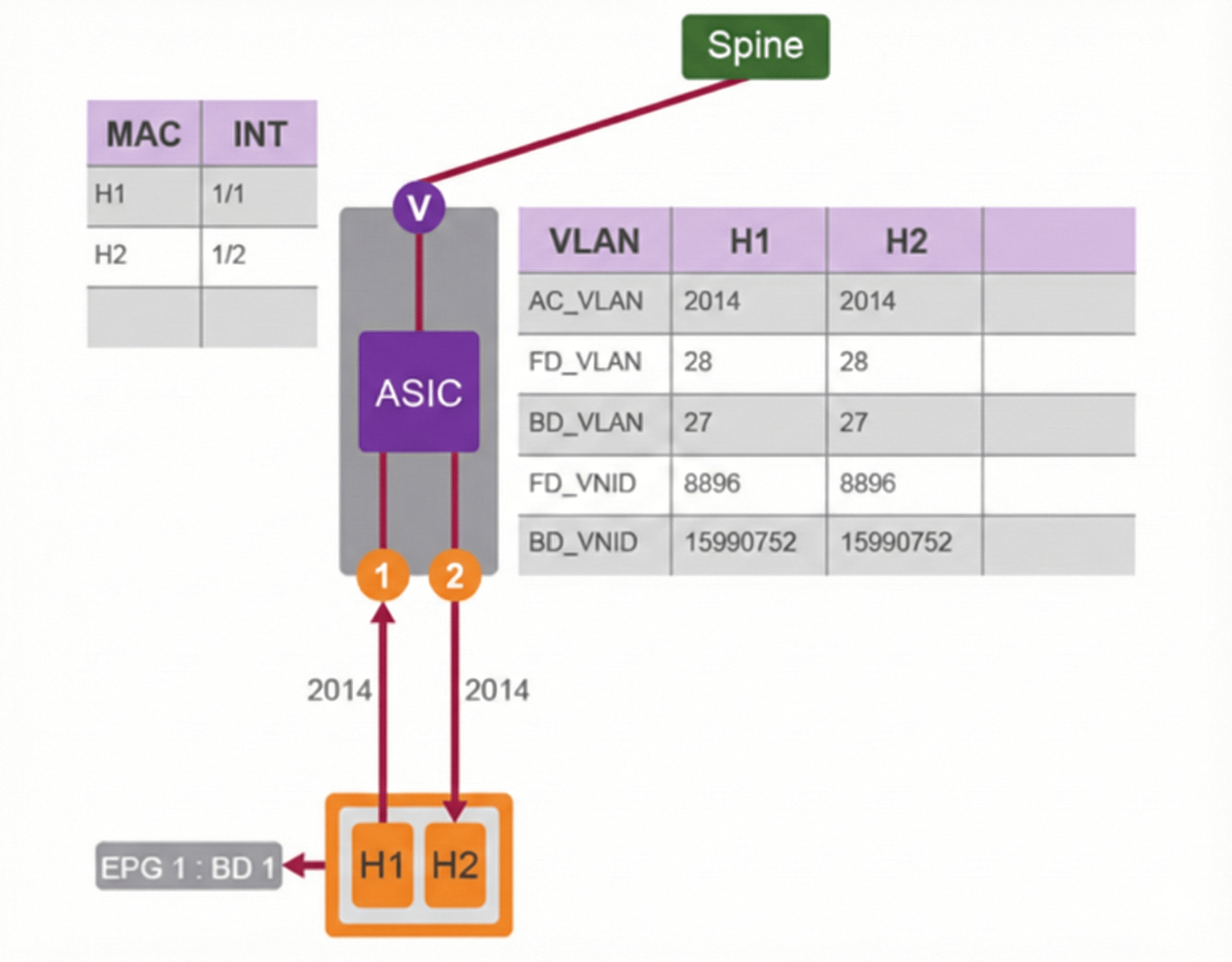
The traffic flow between H1 and H2 is the following:
- H1 sends Layer 2 traffic to H2 with 2014 access encapsulation VLAN.
- Local leaf performs a Layer 2 lookup on the BD_VLAN (on second-generation switches, the MACs are all stored in the scope of BD_VLAN), which is VLAN 27 in this example.
- The leaf bridges the traffic out interface 1/2 with encapsulation 2014.
When the endpoints are connected to different leaf switches, the traffic is sent across the ACI fabric. The following figure shows the behavior on the source leaf switch, when H1 sends traffic to H3.
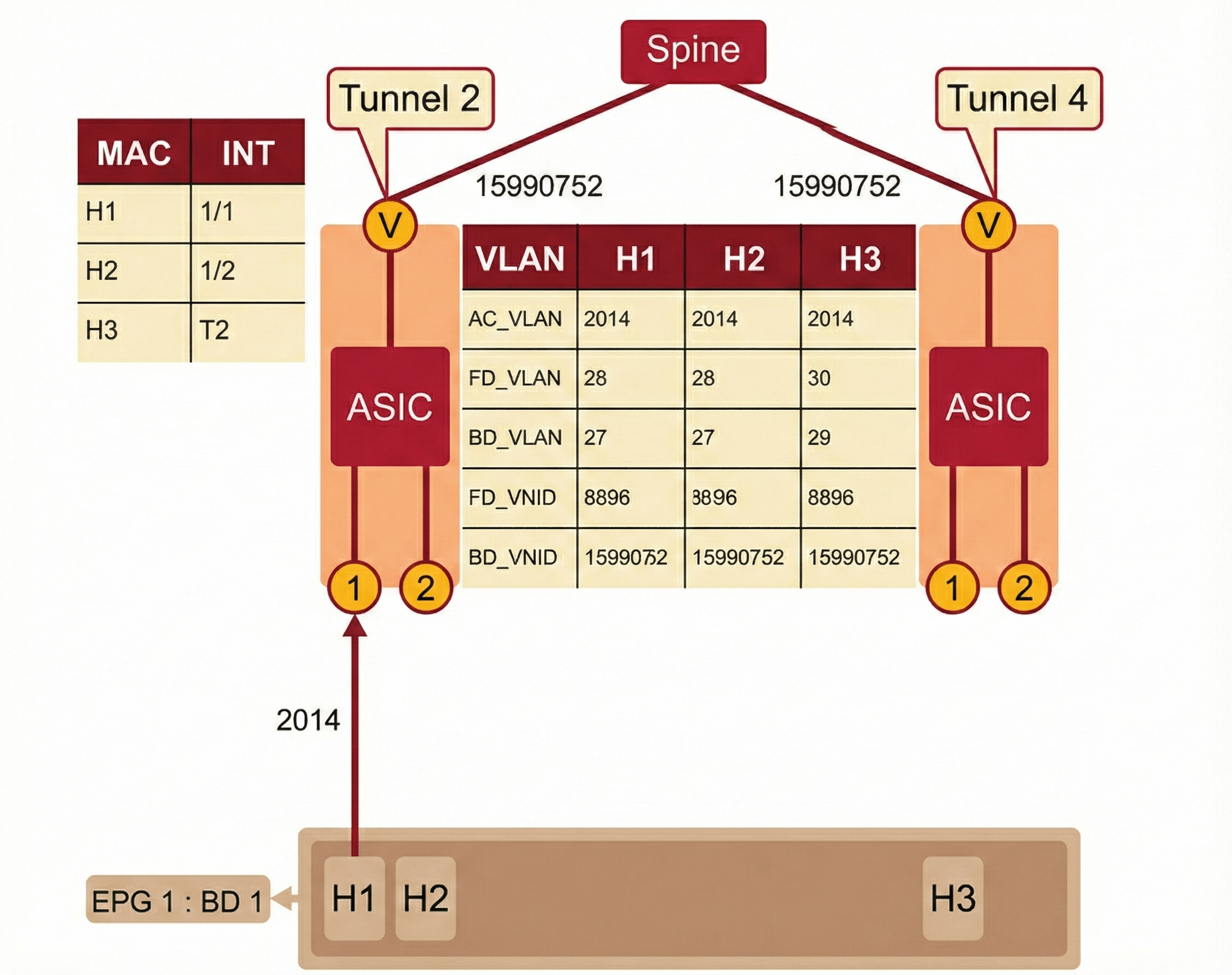
At the begging of the communication between H1 and H3:
- H1 sends Layer 2 traffic to H3 with encapsulation 2014.
- Local leaf performs a normal Layer 2 lookup on the BD_VLAN (ID 27) and sees H3 over interface Tunnel 2.
- Looks in the BD_VLAN (ID 27) for the VNID and forwards the packet out interface Tunnel 2 with the BD_VNID tag, which is 15990752.
Once the traffic is forwarded across the fabric, it reaches the leaf switch where H3 is connected.
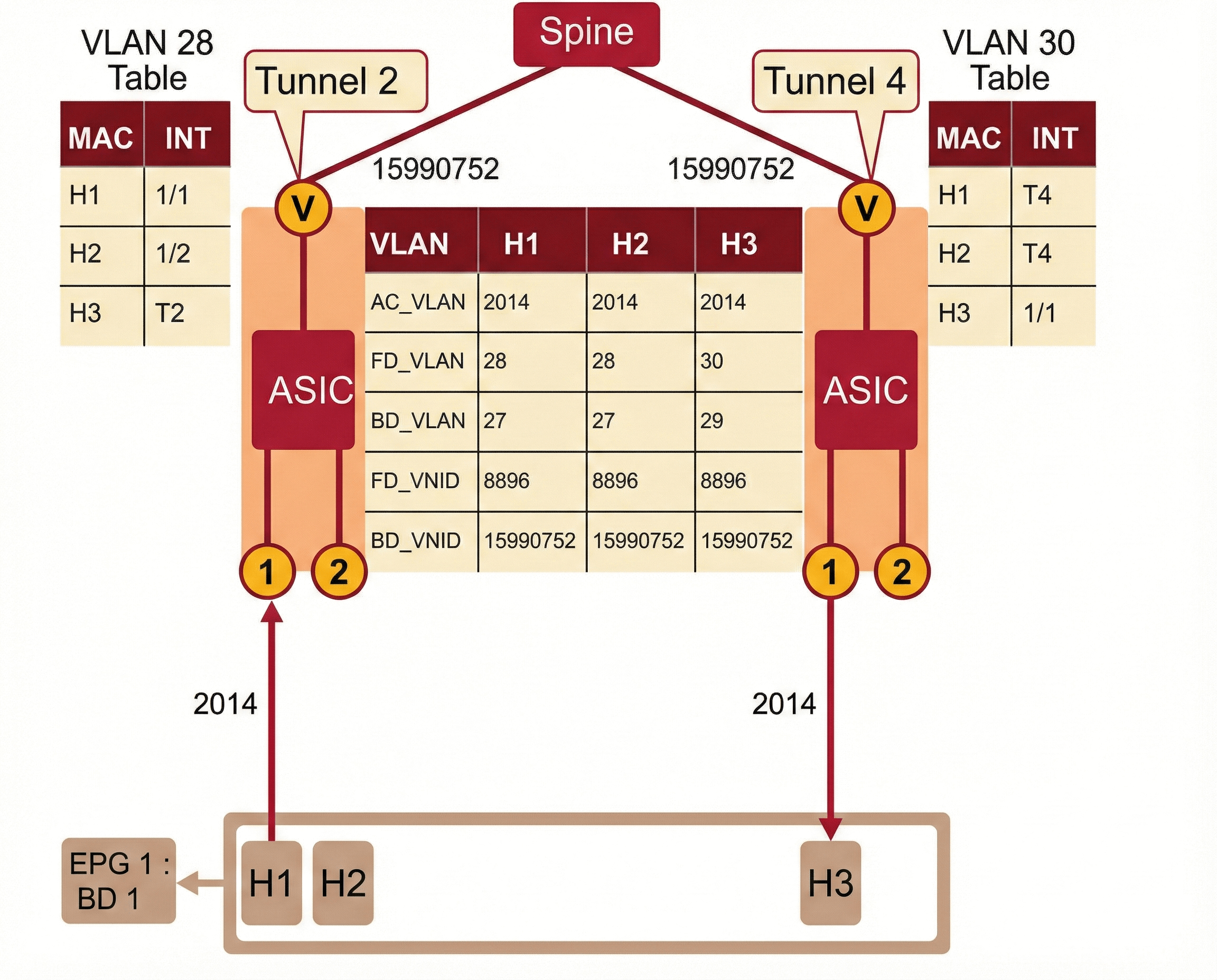
On the H3 leaf switch:
- BD VXLAN packet enters Layer 2 from the spine switch. A reverse lookup is performed in the switch.
- BD_VNID (15990752) is matched to BD_VLAN, then to FD_VLAN (ID 29 and 30 respectively, which are locally significant). BD_VLAN is searched for the connected port of H3. Finally, the traffic is sent out H3, they are tagged with the 2014 access encapsulation VLAN.
Traffic Flow: Same EPG and Bridge Domain, Different Access/Encapsulation
The following examples depict the traffic flow when the endpoints (already known to the fabric) are part of the same EPG and bridge domain (EPG 1 and BD 1), but in a different VLAN access encapsulation. This feature is referred to as a Layer 2 gateway function, where a routing function is not performed at all on a VLAN tag switch. Source and destination MAC addresses do not change and TTL is not decremented. Also, the original Ethernet frame is preserved.

Comment
TABLE OF CONTENTS
RECENT POSTS
- Installing Context-Aware Network Access Control using Cisco ISE Policies
- Designing Network Access Control that is Scalable using Cisco ISE Architecture
- Enterprise Network Access Control and Policy Enforcement using Cisco ISE
- Secure Device Administration and Network Access Using AAA Architecture
- Designing Enterprise-Class Hybrid Cloud Connectivity Using AWS Networking Services
- Exploring Core AWS Networking and Messaging Concepts for Modern Cloud Architectures
- Understanding Key AWS Services for Modern Cloud Architectures
- Building a Strong AWS Foundation with Amazon S3, EC2, and Virtual Private Cloud
- Understanding the ENSDWI Course: Advanced Cisco SD-WAN (Viptela) Concepts
- A Complete Guide to the DCACI-A Course: Mastering Advanced Cisco ACI Concepts


LEAVE A COMMENT
Please login here to comment.