EMAIL SUPPORT
dclessons@dclessons.comLOCATION
USLayer 4–7 Service Insertion Modes
The Layer 4 through Layer 7 devices that you can integrate with the Cisco ACI are typically deployed in a routed mode (Go-To) or transparent mode (Go-Through). Also, they can be used in the service graph in different insertion modes. Thus, you should be familiar with the insertion options, so you can successfully troubleshoot L4-L7 service insertion issues.
The following are Layer 4–7 service insertion modes:
- Unmanaged mode: Offers some configuration automation and simplification. It is commonly used mode, where the configuration of the Layer 4–7 device is performed separately.
- Managed mode: Offers the same benefit as the unmanaged mode, with the added capability of pushing configuration from APIC to a service node via a device package. Still, Cisco ACI device package functionality for L4-L7 devices is deprecated starting from Cisco APIC Release 5.2. The use of configurations without device package (unmanaged mode) is recommended.
- Policy-based redirect (PBR): Utilizes PBR, as one of the main features of the service graph, where the Cisco ACI fabric can redirect traffic between security zones to Layer 4–7 devices. With PBR, the Layer 4–7 device does not need to be the default gateway for the servers, and you do not need to perform traditional networking configuration, such as VRF sandwiching or VLAN stitching.
- Copy services: Unlike SPAN that duplicates all of the traffic, the Cisco ACI copy services feature enables selectively copying portions of the traffic between endpoint groups, according to the specifications of the contract. A copy service is configured as part of a Layer 4 to Layer 7 service graph template that specifies a copy cluster as the destination for the copied traffic. Copy service traffic is managed internally in the switch to minimize impact on normal traffic forwarding.
- Service chaining: The Layer 4–7 service insertion feature enables you to insert more than one service between two EPG, and create a service chain between them.
The following insertion modes are not all mutually exclusive. For example, you can insert Layer 4–7 devices in an unmanaged mode and use the service graph with PBR, and perform additional service chaining if needed.
On the other hand, with the Cisco ACI Layer 4–7 service automation possibilities, the unmanaged and managed modes provide support for different devices and flexibility options, as depicted in this figure.
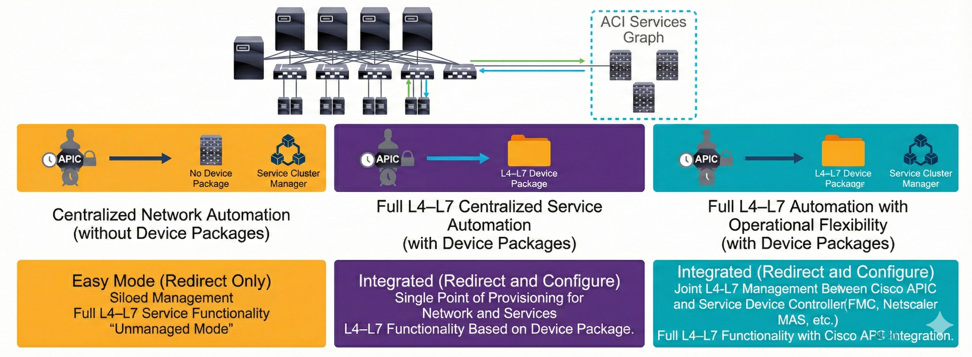
Still, the unmanaged mode is more commonly used, where the APIC allocates only the network resources for the service graph and programs only the fabric (leaf switch) during graph instantiation. This might be needed for various reasons, such as if your environment already has an existing orchestrator or a dev-op tool that is more suitable for programming the service appliance. In some other cases, the device package for the service appliance is not available.
The unmanaged mode for services enables you to choose the APIC's behavior for allocating network resources and programming the fabric. The configuration of the device is left to be done externally by you.
Troubleshooting Service Insertion with PBR
As in traditional network designs, in Cisco ACI fabric the traffic is routed and bridged based on the destination IP and MAC addresses. You can use service graphs with PBR to redirect traffic and send packets to service nodes connected to the fabric, such as firewall, IPS, or load balancer, while overriding the information available in the forwarding table (endpoint table and RIB).
The following figure shows the difference of when ACI routing is used for the east-west traffic between hosts in two EPGs as a part of different bridge domains (before the service graph is deployed) and traffic redirection with the service graph with PBR:
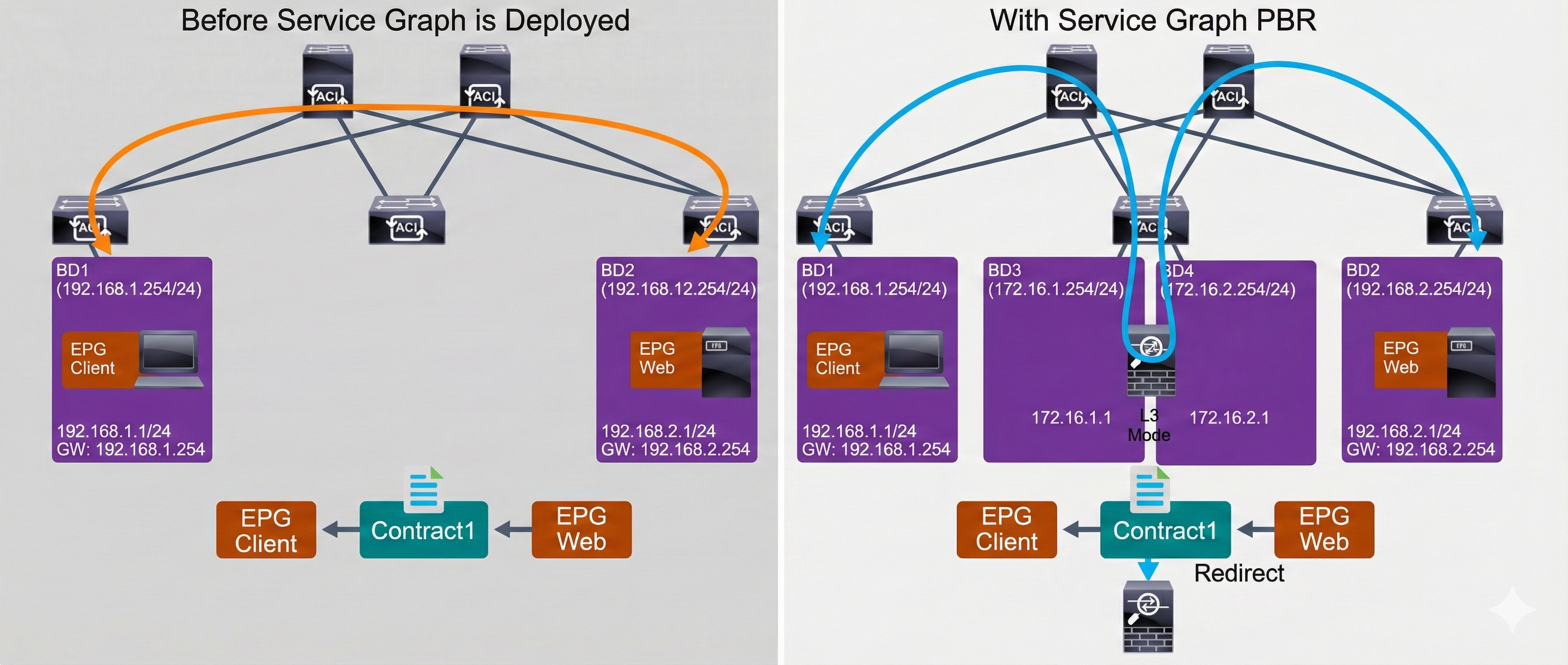
Before the service graph with PBR is deployed, the Cisco ACI relies on routing in the fabric itself to forward the traffic from the client in the EPG client to the server in the EPG web, and allows the traffic that is based on the contract. The default gateway of the client and server is the bridge domain IP address, where these endpoints are deployed.
When the service graph with PBR is used, even though the forwarding table points to the destination endpoint directly, the traffic is redirected to the service node (such as firewall) based on the contract the traffic is hitting. In the contract with the PBR service graph, the traffic redirection is defined towards the service node, which operates in Layer 3 mode and is integrated as service node in the Cisco ACI fabric. It routes and inspects the traffic between the client and server, which is deployed in different EPGs.
A service node can be integrated in Cisco ACI using a service graph without PBR. However, without PBR, the packet flow is still based on the forwarding table, so you must ensure that the forwarding table points to the inserted service node without any redirection, which is typically performed by using VRF stitching (or VRF sandwich in other words).
The PBR configuration in Cisco ACI is almost the same as a normal service graph configuration. The difference is that you need to create and apply the Layer 4–7 PBR policy to define how to redirect the traffic on top of the normal service graph configuration.

Comment
TABLE OF CONTENTS
RECENT POSTS
- Installing Context-Aware Network Access Control using Cisco ISE Policies
- Designing Network Access Control that is Scalable using Cisco ISE Architecture
- Enterprise Network Access Control and Policy Enforcement using Cisco ISE
- Secure Device Administration and Network Access Using AAA Architecture
- Designing Enterprise-Class Hybrid Cloud Connectivity Using AWS Networking Services
- Exploring Core AWS Networking and Messaging Concepts for Modern Cloud Architectures
- Understanding Key AWS Services for Modern Cloud Architectures
- Building a Strong AWS Foundation with Amazon S3, EC2, and Virtual Private Cloud
- Understanding the ENSDWI Course: Advanced Cisco SD-WAN (Viptela) Concepts
- A Complete Guide to the DCACI-A Course: Mastering Advanced Cisco ACI Concepts


LEAVE A COMMENT
Please login here to comment.