EMAIL SUPPORT
dclessons@dclessons.comLOCATION
USOne Apstra Server
Using a single deployment of Juniper Apstra software, you can create multiple blueprints (Apstra-managed networks) based on any combination of data center and Freeform reference designs.
Tthe Freeform reference design is available to build and manage your network. To get the full benefits of working with Apstra, the data center reference design is the preferred way to implement your network.
Some benefits are:
- You can use Apstra to manage various vendor devices.
- You do not need to know vendor syntax (Junos, Cisco NX-OS, and so on).
- You can design your network prior to determining the vendor (logical devices).
- You can use connectivity templates to add overlay networks across the entire topology.
- You can deploy routing and security policy for the entire network from the UI.
- You can view real-time device telemetry as it is being collected by the Apstra server. — Liveness, config, interface, cabling, BGP, link aggregation group (LAG), multichassis LAG (MC-LAG), hostname, and the routing tables (also known as routing information base [RIB])
- You can use time voyager to roll your whole data center back to a previous configuration. You can use the revert function to clear any staged changes.
- You can use the Representational State Transfer (REST) API to interact with the Apstra server.
- You can view each device's incremental configuration (see a device's configuration before Apstra pushes it to the device).
- You can rely on Apstra to automatically fix the cable map on spine-to-leaf links.
Juniper Apstra Data Center Networking
The Juniper Apstra data center reference is a combination of rack types, templates, and blueprints. The Juniper Apstra server can manage multiple blueprints (collapsed, three-stage, or five-stage IP fabrics). A blueprint is a running IP fabric that is managed by Juniper Apstra. Prior to becoming a blueprint, you can describe what you expect a blueprint to comprise by first configuring rack types and a template. A template (and its associated rack types) is a way of defining what you want your 3-stage fabric to comprise (possibly a row in your data center), including how many spine nodes, how many leaf nodes, how many servers, and all of their network connectivity. Once you define a template, you can then instruct Juniper Apstra, for example, to create 10 blueprints using that template as a guide.
Designing a Data Center Blueprint
You can assign all devices managed by Juniper Apstra one of seven roles; superspine node, spine node, leaf node, superspine, access switch, peer device, generic system, or unused. A generic system is usually a server or an external router. You should know that Juniper Apstra does not configure or manage those devices. However, regarding the generic systems, Juniper Apstra configures the connectivity and routing (on the spine or leaf nodes) to send and receive traffic from the generic devices. You must provide some basic information to the Juniper Apstra server about the generic system, which may include an external router's AS number and loopback interface address.
Generic systems can be considered L2 or Layer 3 (L3). In either case, you must manually configure the device with IP addressing and routing. The attached leaf nodes handle traffic in and out of an L2 device at Layer 2 (switched locally, forwarded over a VXLAN tunnel to and from remote leaf node, forwarded over a VLAN to/from the core). The leaf node will route traffic to and from an L3 device.
The below figure shows that early in the design process; you create the various rack types that you will apply to your templates. You give each rack type a name, allot one or two top-of-rack switches to support traffic to and from the generic systems in the rack, and have zero or more generic devices attached to the top-of-rack switches.
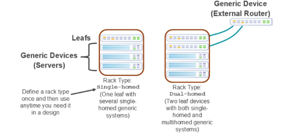
The first example shows a rack type that we have named Single-homed . This is a custom rack design that uses a single top-of-rack switch and can support multiple single-homed generic systems. With a rack design that uses a single top-of-rack switch, you can attach the generic systems to that switch using a single link or multiple links using link aggregation (with or without Link Aggregation Control Protocol [LACP]).
The second example shows a rack type that we have named Dual-homed . This is a custom rack design that uses two top-of-rack switches and can support multiple single-homed generic systems, multiple dual-homed generic systems, or both. With a rack design that uses two top-of-rack switches, you can attach the single-homed generic systems to either switch using a single link or multiple links using link aggregation (with or without LACP). You can attach the dual-homed generic systems using one link or multiple links to each of the top-of-rack switches. With dual-homed generic systems, the top-of-rack switches will use either MC-LAG or Ethernet segment identifier (ESI) LAG (with or without LACP) to support the multihoming.

Comment
TABLE OF CONTENTS
- Navigating Apstra UI
- Configure : Logical Devices, Device Profiles, and Interface Maps
- Managing Devices
- Creating Resources and Tags
- Configuring Racks
- Configuring Templates
- Building and Deploying a Blueprint From a Template
- Working With The Active Blueprint
- Enabling Property Sets & Configlets
- Configuring Connectivity Templates
- Configuring Multitenancy
RECENT POSTS
- Installing Context-Aware Network Access Control using Cisco ISE Policies
- Designing Network Access Control that is Scalable using Cisco ISE Architecture
- Enterprise Network Access Control and Policy Enforcement using Cisco ISE
- Secure Device Administration and Network Access Using AAA Architecture
- Designing Enterprise-Class Hybrid Cloud Connectivity Using AWS Networking Services
- Exploring Core AWS Networking and Messaging Concepts for Modern Cloud Architectures
- Understanding Key AWS Services for Modern Cloud Architectures
- Building a Strong AWS Foundation with Amazon S3, EC2, and Virtual Private Cloud
- Understanding the ENSDWI Course: Advanced Cisco SD-WAN (Viptela) Concepts
- A Complete Guide to the DCACI-A Course: Mastering Advanced Cisco ACI Concepts


LEAVE A COMMENT
Please login here to comment.