EMAIL SUPPORT
dclessons@dclessons.comLOCATION
USSD-Access Wireless Architecture
SD-Access Wireless:
When we integrate the Wireless in SD-Access Infrastructure to get benefits of all SD-Access fabric, we say it SD-Access Wireless.
Some of the benefits of SD-Access Wireless are:
- Centralized Wireless Control plane
- Optimized Distributed Data Plane at Edge switch
- Seamless L2 Roaming everywhere within Mobility Group.
- Simplified Guest & Mobility tunneling
- Policy Simplification for both wired and wireless Clients
- Easy Segmentation between Wired and Wireless Network
- Investment Protection by supporting existing AireOS WLC, Optimized for 802.11ac Wave 2 APs and also supports Wave 1 APs.
Wireless Integration in SD-Access:
There are two options to integrate Wireless Access in SD-Access Wired Network fabric.
- SD-Access Wireless Architecture
- CUWN Wireless Over the Top (OTT)
Let’s discuss each and every options in details.
SD-Access Wireless Architecture:
In this SD-Access Wireless Architecture , Control plane is centralized and to achieve that CAPWAP tunnel is created between AP and WLC , and data plane is distributed using VXLAN directly from fabric enabled APs. WLC and AP both are part of SD-Access Fabric, AP is connected to Fabric Overlay (EID) as special clients.
Below figure describes about SD-Access Wireless Architecture.
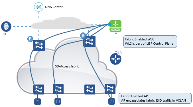
SD-Access Wireless Architecture Components:
Below are SD-Access Wireless Architecture components and are discussed in details.
Control plane node:
- It is based on LISP MS/MR and contain host EID database to provide Overlay reachability information of each EID in fabric.
- CP contains the HDB which tracks EID to edge node connectivity along with other attributes.
- CP supports multiple EID lookup like IPV4/32, IPV6/128 or MAC address
- It receives the EID information from Edge node connected directly and for wireless clients WLC will inform to CP.
- It resolves the lookup requests from remote edge node to locate end points
- It updates Fabric Edge node and border node and border node with wireless client mobility and RLOC information.
Fabric Edge Node:
Below are the roles and responsibility of Fabric Edge Switch.
- It identifies and Authenticates Wired End Points
- It registers IPV4/IPV6 Endpoint information with Control plane node.
- Provides AnycastL3 Gateway for connected Endpoints
- Provides VN services for wireless Clients
- It onboard AP in to fabric and also creates the VXLAN tunnel with AP for data traffic
- It provides access to Guest Traffic with Guest Border and Guest Control plane node.
Fabric Border Node:
This Border node is used for all traffic which is entering and leaving the SD-Access Fabric.
There are two types of Border nodes.
- Fabric Border: It adds the known IP/mask routes to the map system and this Known routes are further advertised to your fabric nodes, Remote WLC, Shared Services DC, Branch, private cloud.
- Default Border: It is used for unknown routes mostly for Internet & Public Cloud and act as a gateway of last resort.
Border is responsible for translation of context VRF and SGT for one domain to another.
Fabric Enabled WLC:
Fabric enabled WLC is integrated with LISP control plane. This WLC is responsible for AP image /Config, Radio Resource Management, Client Session management and roaming and all other wireless control plane functions.
For WLC Fabric Integration:
- Wireless Client MAC address is used as EID
- It inform about Wireless MAC address with its other information like SGT and Virtual Network Information
- VN information is mapped to VLAN on FEs
- WLC is responsible for updating Host Database tracking DB with roaming information
Fabric Enabled AP
- It is local mode AP, and is connected directly to edge switch.
- From AP to WLC, CAPWAP tunnel is formed using Fabric as transport.
- Fabric is enabled per SSID.
- For fabric Enabled SSID, AP converts 802.11 traffic to 802.3 and then encapsulate it to VXLAN with proper VNI and SGT info to the client.
- AP upon receipt of traffic, forwards it based on forwarding table programmed by WLC using VXLAN tunnel to first hop Fabric destination edge switch.
- SGT and VRF based policies for wireless users on fabric SSID are applied at fabric edge
- For Fabric enabled SSID , user data plane is distributed at AP using VXLAN encapsulation
- All wireless feature like AVC, QOS is applied by AP.
SD-Access Wireless Protocols and Communication Interfaces:
Below figure describe the Wireless Protocols and communication Interfaces.
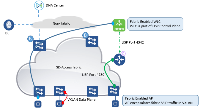
- Between WLC & AP: Control plane communication via CAPWAP tunnel similar to existing mode.
- Between AP to Switch: Data traffic is switched from AP to Edge Switch using VXLAN tunnel encapsulation, with UDP port 4789.
- Between WLC and Control plane node: WLC communicates to Control plane running on TCP port 4342 on controller.
- DNAC to WLC: In first release, DNAC uses CLI interface to configure WLC.
- Switch to Control plane Node: They both communicates via TCP port 4789.
SD-Access Wireless Platform Support:
SD-Access support WLC with AireOS release 8.5 and higher
- AIR-CT3504
- AIR-CT5520
- AIR-CT 8540
This architecture is also optimized for Wave 2 11ac access point in local mode: AP1810, Ap1830, AP1850, AP2800, and AP3800.
SD-Access Wireless Network deployment:
Below are some consideration that needs to be taken while deploying the SD-Access Wireless network.
Access point:
- AP will be directly connected to Fabric Edge Switch or to an external node switch
- AP is part of fabric Overlay
- AP will be part of INFRA-VN which will be further mapped to Global routing table
- AP will join to WLC in Local Mode.
For Wireless LAN Controller:
- WLC is connected to outside fabric or can also be connected directly to Border switch
- WLC should be routed and reachable via Global Routing table.
- There is no need for inter-VRF leaking for AP to join WLC
- WLC can only communicate to one Control Plane Node (two for redundancy) and only one WLC can always be part of only one fabric Domain.
Below Figure describes the above communication points mentioned.
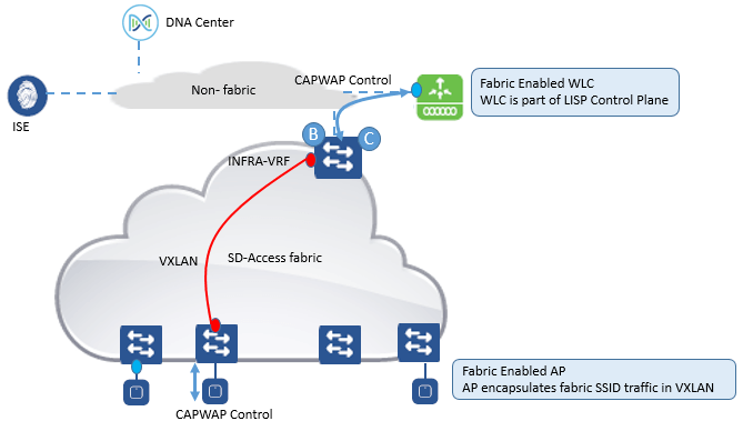
AP to WLC Communication:
In this Scenario and SD-Access infrastructure , AP are connected to Fabric Edge and are on Overlay network while WLC resides outside SD-Access fabric in traditional network.
Now in order to reach AP and WLC , WLC subnet will be advertised in to Underlay routing so that nodes like fabric edge and Control plane will be able to reach WLC via native routing. AP subnets will be part of Overlay network and will be advertised to external network so that WLC can reach to AP via Overlay.
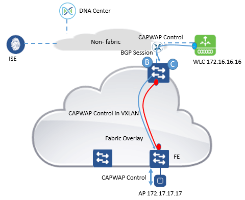
Now let’s see how CAPWAP tunnel is created between AP and WLC for fabric enabled SSID.
Let see how Traffic from AP to WLC or we say it South-North direction CAPWAP traffic flows by below figure
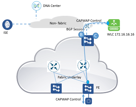
Border node either internal or external will redistribute WLC route in underlay IGP routing.
Fabric Edge will learn these WLC route in its global routing table
Now When Fabric Edge receives CAPWAP packet from AP , FE will check its GRT and packet is forwarded with no VXLAN encapsulation, CAPWAP traffic will travel from AP to WLC via Underlay.
Now We will see how North to South CAPWAP traffic flow from WLC to AP by below figure
- AP subnet is registered in Control plane and is part of overlay.
- Border Node will export this AP EID from CP to Global routing table and will also import the AP routes in to LISP map cache entry.
- Border Node will advertise local AP EID to external domain.
- When border receives CAPWAP packet from WLC , it will lookup LISP table and traffic will be sent to FE with VXLAN encapsulation.
- Now CAPWAP traffic from WLC to AP travel sin overlay network.
Comment
TABLE OF CONTENTS
RECENT POSTS
- Understanding Cisco ISE Authentication and Authorization Policies
- Installing Context-Aware Network Access Control using Cisco ISE Policies
- Designing Network Access Control that is Scalable using Cisco ISE Architecture
- Enterprise Network Access Control and Policy Enforcement using Cisco ISE
- Secure Device Administration and Network Access Using AAA Architecture
- Designing Enterprise-Class Hybrid Cloud Connectivity Using AWS Networking Services
- Exploring Core AWS Networking and Messaging Concepts for Modern Cloud Architectures
- Understanding Key AWS Services for Modern Cloud Architectures
- Building a Strong AWS Foundation with Amazon S3, EC2, and Virtual Private Cloud
- Understanding the ENSDWI Course: Advanced Cisco SD-WAN (Viptela) Concepts


LEAVE A COMMENT
Please login here to comment.