EMAIL SUPPORT
dclessons@dclessons.comLOCATION
USForwarding & QOS Concepts
Without QOS, Traffic flow over IPsec connection using default data packing forwarding method. Now if you want to modify this default data packet forwarding, you need to create and apply the centralized data policy or localized data policy.
With Centralized data policy any traffic can be permitted or blocked based on address, port, and DSCP fields in IP packets. And with Localized data policy flow of data traffic is controlled from vEdge router in and out interface by QOS and Mirroring etc.
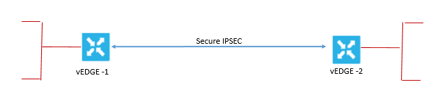
When the control plane connections of the Cisco SD-WAN overlay network are operating, data traffic flows automatically over the IPsec connections between the routers. Because data traffic never goes to or through the centralized Cisco vSmart controller, data forwarding occurs only between the Cisco WAN Edge devices as they send and receive data traffic.
The routing protocols that are running in the control plane provide a router with the best route to reach the network that is on the service side of a remote router. However, in some situations it is beneficial to choose more specific routes. Using forwarding, you can affect the flow of data traffic. Forwarding takes the data packet and sends it over the transport to the remote side, specifying what to do with the packet. It specifies the interface through which packets are sent to reach the service side of a remote router.
To modify the default data packet-forwarding flow, you need to create and apply a centralized or localized data policy. With a centralized data policy, you can manage the paths along which the traffic is routed through the network. You can also permit or block the traffic based on the address, port, and DSCP fields in the packet’s IP header. With a localized data policy, you can control the flow of data traffic into and out of the interfaces of a router, enabling features such as QoS and mirroring.
Default Behavior without data policy:
When no centralized data policy is configured on the Cisco vSmart controller, all data traffic is transmitted from the local service-side network to the local router. It is then routed to the remote router and to the remote service-side network, with no alterations in its path. When no access lists are configured on the local router to implement QoS or mirroring, the data traffic is transmitted to its destination with no alterations to its flow properties.
Let’s understand the Data policy default Behavior by below dig, the below dig its self explains how packet header changes while using the default data policy behavior.
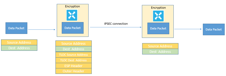
A data packet that is arriving from the local service-side network and is destined for the remote service-side network comes to the first WAN Edge router. The packet has a source IP address and a destination IP address. The WAN Edge router looks up the outbound security association in its VPN route table, and the packet is encrypted with the security association and gets the local TLOC. The WAN Edge router previously received its security association from the Cisco vSmart controller. There are two security associations for each source and destination TLOC pair. More specifically, every local TLOC has two security associations for every remote TLOC: one that is outbound for encryption and one that is inbound for decryption.
The Encapsulating Security Payload (ESP) adds an IPsec tunnel header to the packet. An outer header is added to the packet. At this point, the packet header contains the following information:
-
TLOC source address
-
TLOC destination address
-
ESP header
-
Destination IP address
-
Source IP address
The WAN Edge router checks the local route table to determine the interface that the packet should use to reach its destination. The data packet is sent out on the specified interface, onto the network, to its destination. At this point, the packet is being transported within an IPsec connection.
When the packet is received by the WAN Edge router on the remote service-side network, the WAN Edge router removes the TLOC source address and TLOC destination address header fields. It then uses the inbound security association to decrypt the packet. The remote WAN Edge router looks up the destination IP address in its route table to determine the interface to use to reach to the service-side destination.
Behavior changes while using QOS Data Policy:
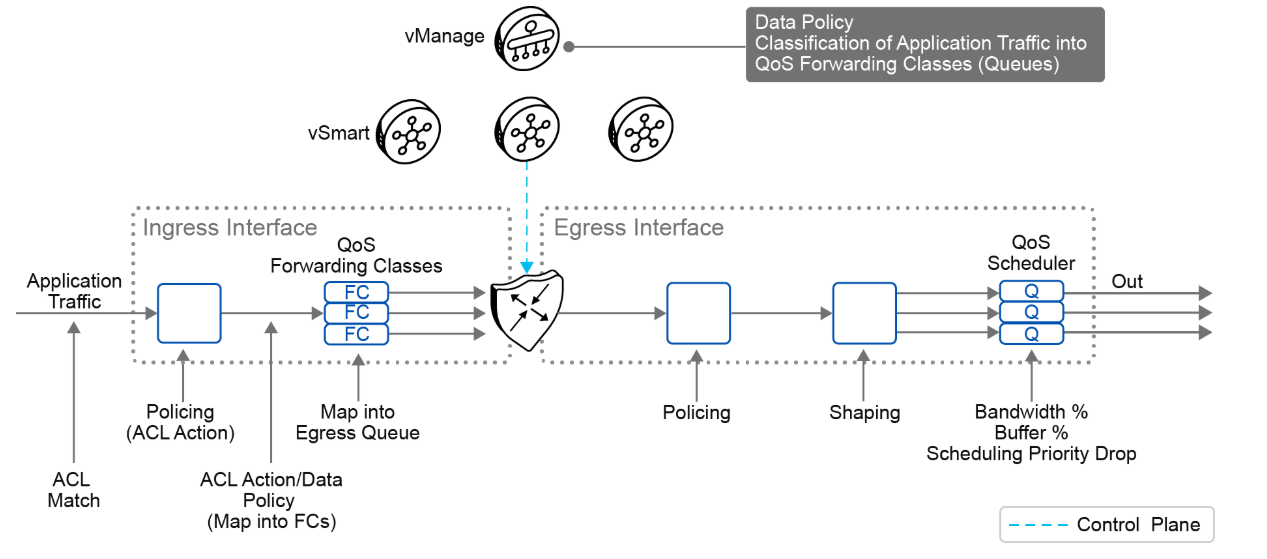
The below fig explains about QOS policy that can be applied to data policy when any data packet is transmitted from one vEdge router to another. When Policy is marked input are applied on inbound interface and when it is marked output are applied on outbound interface to vEdge Router before packets are transmitted out the IPSEC tunnel.
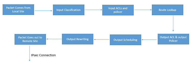
The direction for policy implementation is defined with respect to the WAN Edge routers in the network. You can have policies for packets coming in on an interface or for packets going out of an interface. The figure shows the QoS policies that you can apply to a data packet as it is transmitted from one branch to another. The policies that are marked as Input are applied on the inbound interface to the WAN Edge router. The policies that are marked as Output are applied on the outbound interface to the WAN Edge router before the packets are transmitted out the IPsec tunnel.
Use the following procedure to configure QoS:
-
Define a class map to classify packets, by importance, into the appropriate forwarding classes. Reference the class map in an access list.
-
Define a policer to specify the rate at which the traffic is sent on the interface. Reference the policer in an access list, and apply the access list on an inbound interface. The WAN Edge router checks the local routing table to identify the interface that the packet should use to reach its destination.
-
Define the policer and reference the policer in an access list. Apply the access list on an outbound interface.
-
Define a QoS map to define the priority of data packets. Apply the QoS map on the outbound interface.
-
Define a rewrite rule to overwrite the DSCP field of the outer IP header. Apply the rewrite rule on the outbound interface.
On the Viptela operating system WAN Edge virtualized routers, each interface has four queues, which are numbered from 0 through 3. Queue 0 is reserved for control traffic, and queues 1, 2, and 3 are available for data traffic. The scheduling method for all four queues is WRR. LLQ is not supported.
How QOS works:
The QoS feature on the WAN Edge routers works by examining packets that are entering at the edge of the network. With a localized data policy, also called access lists, you can provision QoS to classify incoming data packets into multiple forwarding classes based on importance, spread the classes across various interface queues, and schedule the transmission rate level for each queue. The access lists can be applied in either the outbound or inbound direction on the interface. In the outbound direction, the data packet travels from the local service-side network into the IPsec tunnel and toward the remote service-side network. In the inbound direction, the data packets are exiting from the IPsec tunnel and being received by the local router.
To provision QoS, you must configure each router in the network. Generally, each router on the local service-side network examines the QoS settings of the packets that enter it and determines which class of packets are transmitted first. It then processes the transmission based on those settings. As packets leave the network on the remote service-side network, you can rewrite the QoS bits of the packets before transmitting them to meet the policies of the targeted peer router.
You can classify incoming traffic by associating each packet with a forwarding class. Forwarding classes group data packets for transmission to their destination. Based on the forwarding class, you assign packets to output queues. The routers service the output queues according to the associated forwarding, scheduling, and rewriting policies that you configure.
You can configure a QoS map for each output queue to specify the bandwidth, delay buffer size, and packet loss priority of output queues. This configuration allows you to determine how to prioritize data packets for transmission to the destination. Depending on the priority of the traffic, you can assign packets the higher or lower bandwidth, buffer levels, and drop profiles. Based on the conditions that are defined in the QoS map, the packets are forwarded to the next hop.
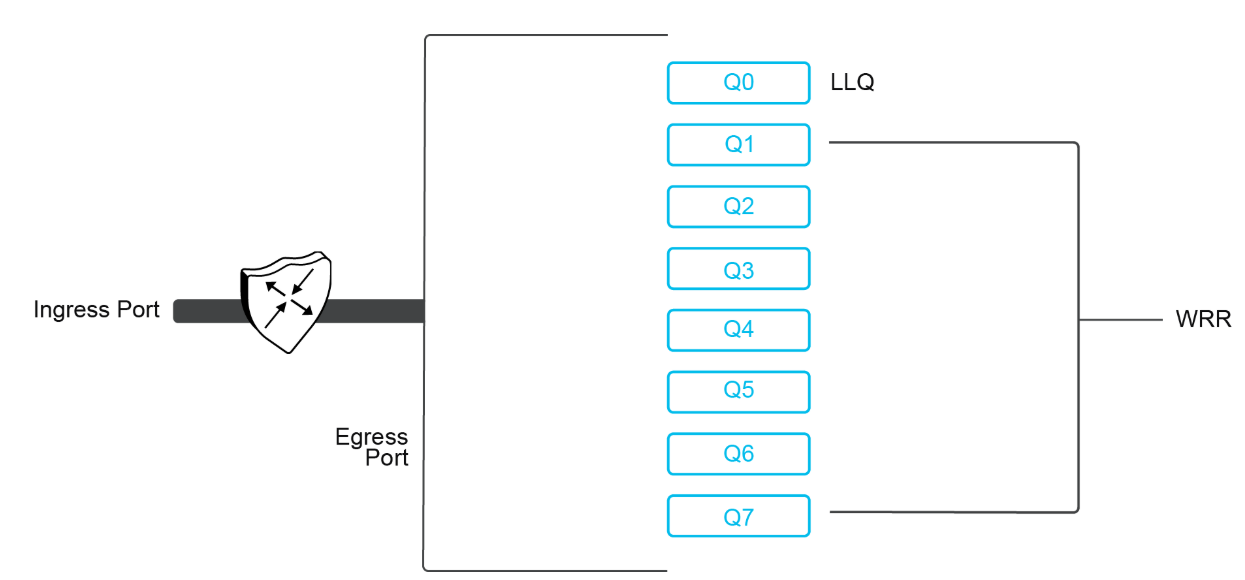
On the WAN Edge routers, each interface has eight queues, which are numbered 0 to 7. Queue 0 is reserved and is used for both control traffic and low-latency queuing (LLQ) traffic. For LLQ, any class that is mapped to queue 0 must also be configured to use LLQ. Queues 1 to 7 are available for data traffic, and the default scheduling for these seven queues is weighted round robin (WRR). For these queues, you can define the weighting according to the requirements of your network. When QoS is not configured for data traffic, queue 2 is the default queue.
You can configure and apply rewrite rules on the egress interface to overwrite the DSCP value for packets entering the network. With rewrite rules, you can map traffic to code points when the traffic exits the system. Rewrite rules use the forwarding class information and packet loss priority that is used internally by the WAN Edge routers to establish the DSCP value on outbound packets. You can then configure algorithms such as random early detection (RED) or weighted random early detection (WRED) to set the probability that packets will be dropped based on their DSCP value.
You can configure policers to control the maximum rate of traffic that is sent or received on an interface and to partition a network into multiple priority levels. The traffic that conforms to the policer rate is transmitted, and the traffic that exceeds the policer rate is sent with a decreased priority or is dropped. You can apply a policer to inbound or outbound interface traffic. The policers that are applied to inbound interface traffic allow you to conserve resources by dropping traffic that does not require being routed through the network. The policers that are applied to outbound interface traffic control the amount of bandwidth that is used.
You can configure the shaping to control the maximum rate of traffic that is sent. You can configure the aggregate traffic rate on an interface to be less than the line rate, so that the interface transmits less traffic than it is capable of transmitting. You can apply shaping to outbound interface traffic.
Marking and Re-marking Packets
A packet on the transport network is in a tunnel. Therefore, the packet has two headers: the inner, original packet header, and the outer tunnel header. Both headers have a DSCP value.
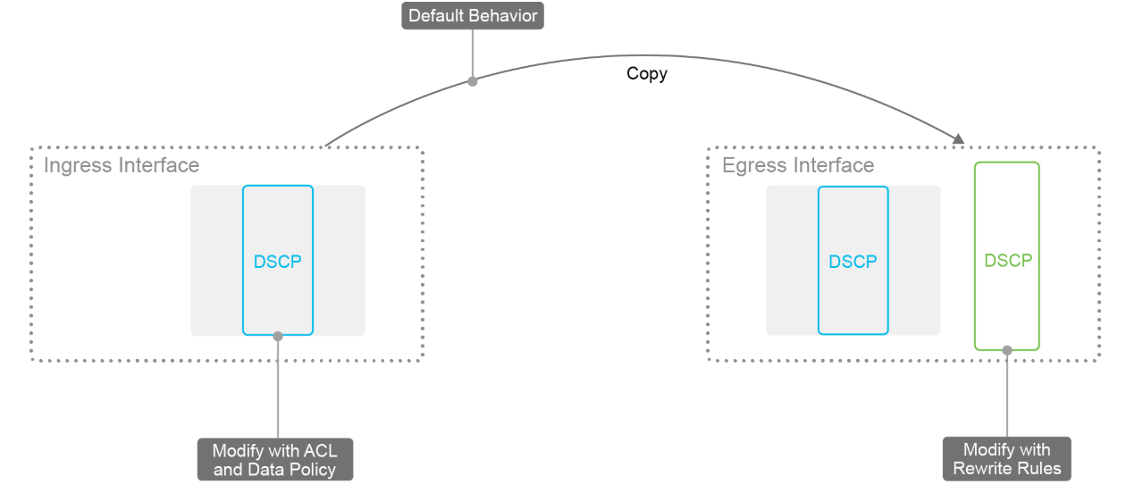
The packets have the following characteristics:
-
They comply with the service providers' provisioned classes of service.
-
Ingress classification is DPI or 6-tuple matching with the use of a centralized or localized data policy.
-
Ingress interface marks and re-marks inner DSCP bits.
-
Inner DSCP bits are copied to the outer DSCP bits.
-
Egress interface rewrite rules re-mark outer DSCP bits.
A normal best practice is to copy the inner DSCP bits to the outer packet header of the tunnel packet at the time of encapsulation. This behavior is the default, and you do not need to configure it. This concept works only if the QoS management is the same in the service network as on the transport network (which is why you should use standard QoS classes if possible). If the transport network has a different way of handling the DSCP values, the packets might require re-marking. In this process, the inner-packet classification is handled exactly as before, but additional re-marking occurs on the egress interface.
Shaping
Traffic shaping aligns a packet flow to a specific forwarding rate by delaying and queuing some packets.
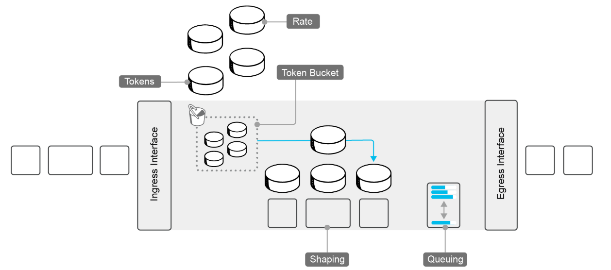
The shaping characteristics are as follows:
-
Shaping is effective on egress physical interfaces.
-
Shaping is not supported on subinterfaces on VLANs.
-
-
Forward traffic conforms to a configured shape rate.
-
Tokens are in the bucket.
-
-
Queue traffic exceeds a configured shape rate.
-
No Tokens are in the bucket.
-
Weighted round-robin
-
-
Configured in kbps
Because traffic shaping applies only to physical interfaces and is not supported on subinterfaces or VLANs, the configuration is simple. Traffic that exceeds the shaping rate is queued (instead of being dropped when policing is configured). A Token Bucket algorithm determines the shaping rate. At a fixed rate, tokens are placed in an imaginary bucket. Whenever a packet is transmitted, a token is removed from the bucket. When a packet is scheduled to be sent and no token is in the bucket, the packet is held until tokens are available again. By using this method, you can achieve a maximum data rate and effectively throttle traffic.
Policing
During policing, traffic that exceeds the configured rate is dropped or reclassified.
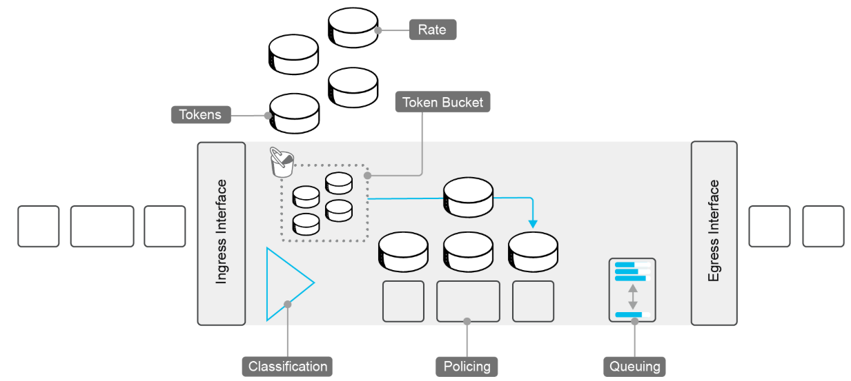
The policing characteristics are as follows:
-
Ingress and egress policing:
-
It is interface- and subinterface-based.
-
DPI or 6-tuple matching, using centralized or localized data policy.
-
-
Forward traffic conforms to the configured policer rate.
-
Drop traffic that exceeds the configured policer rate.
-
Configurable burst rate. Token bucket depth.
Also, in this example, the Token Bucket algorithm is used. If there are no tokens, the packets are dropped or are sent with a lower priority. Traffic policing is also supported on subinterfaces, and you can use a data policy to classify packets. The depth of the bucket determines how many packets can be sent continuously. If five tokens are in the bucket, the next five packets can be sent without delay. Therefore, the token bucket depth determines the burst rate.

Comment
TABLE OF CONTENTS
- Onboarding & Provisioning Configuring Templates
- Authentication between vSmart & vBond
- Authentication between vSmart Controller
- Authentication between vBond & vEdge Router
- Authentication between vEdge Router & vManage NMS
- Authentication between vSmart Controller & vEdge Router
- Viptela Specific Port Terminology
- Deploy & Configure vManage & Generate Certificate
- Deploy & Configure vBond & Generate Certificate
- Deploy & Configure vSmart & Generate Certificate
- Configure vEdge & Generate Certificate
- SDWAN & NAT
- Secure DataPlane Bringup
- Enterprise CA for SDWAN Instances
- ZTP Process & PnP Overview
- Control Plane & Data Plane Operation - Unicast Routing Overview
- Configuring OMP & Its attributes
- Configure Unicast Overlay Routing
- Routing Configuration Example
- Segmentation Overview
- Configuring Segmentation
- Segmentation Configuration Example
- Data Traffic across Private WANs
- NAT in SDWAN & Data Encryption
- SD-WAN Viptela Policy Overview
- SD-WAN Centralized & Localized Control Policy Overview
- SD-WAN Centralized & Localized Data Policy
- Service Chaining
- Traffic Flow Monitoring
- vEdge Router as NAT Device
- Zone Based Firewalls
- Configure Centralized Control Policy
- Configuring Centralized Data Policy
- Configuring Cflowd Traffic Monitoring
- Configuring Zone based Firewall
- Service Chaining Configuration Example
- Configuring Service Side NAT
- Configuring Transport side NAT
- Control Policy Example 1: Hierarchical Topology
- Multi-Region Fabric
- Control Policy Example 2: Implementing Traffic Engineering
- Control Policy Example 2: Dynamic On-Demand Tunnels
- LAB Deploy Cisco SD-WAN Edge Routers
- LAB Deploy SDWAN Controllers
- LAB Deploy Cisco SD-WAN Devices Using Configuration Group
- LAB Implement Service-Side Routing Protocols
- LAB Implement TLOC Extensions
- LAB Implement Control Policies
- LAB Implement Data Policies
- LAB Implement Application-Aware Routing
- LAB Implement Branch and Regional Internet Breakouts
- LAB Migrate Branch Sites
RECENT POSTS
- Installing Context-Aware Network Access Control using Cisco ISE Policies
- Designing Network Access Control that is Scalable using Cisco ISE Architecture
- Enterprise Network Access Control and Policy Enforcement using Cisco ISE
- Secure Device Administration and Network Access Using AAA Architecture
- Designing Enterprise-Class Hybrid Cloud Connectivity Using AWS Networking Services
- Exploring Core AWS Networking and Messaging Concepts for Modern Cloud Architectures
- Understanding Key AWS Services for Modern Cloud Architectures
- Building a Strong AWS Foundation with Amazon S3, EC2, and Virtual Private Cloud
- Understanding the ENSDWI Course: Advanced Cisco SD-WAN (Viptela) Concepts
- A Complete Guide to the DCACI-A Course: Mastering Advanced Cisco ACI Concepts


LEAVE A COMMENT
Please login here to comment.