EMAIL SUPPORT
dclessons@dclessons.comLOCATION
USControl Policy Example 2: Dynamic On-Demand Tunnels
Since software versions 20.3.1 and 17.3.1, Cisco SD-WAN supports dynamic on-demand tunnels between any two Cisco SD-WAN spoke devices. These tunnels are triggered to be set up only when there is traffic between the two devices. After the traffic flow between the devices stops, a user-configurable inactivity timer starts, and after the configured time, the tunnel between the devices is removed. The on-demand link between the two devices is then considered to be inactive. In this inactive state, it does not use network bandwidth and does not affect device performance.
To enable two spoke device peers to use on-demand tunnels, they must have an alternate route or a backup route through a hub. Using the backup route, either spoke device can resume traffic flow between the two spokes, which reactivates the tunnel to handle the traffic directly from peer to peer.
The on-demand tunnels offer the following advantages:
-
Improved performance, especially for less-powerful platforms operating in a full-mesh network.
-
Improved latency in hub-and-spoke deployments when on-demand tunnels are used between spokes.
-
Reduced bandwidth usage in the network because tunnels in the Inactive state do not require BFD probes, so there is less BFD traffic produced in the network.
-
Direct tunnels between spokes, while also optimizing CPU and memory usage.
Dynamic On-Demand Tunnel Mechanism in Detail
When you configure a site to use dynamic tunnels, the on-demand functionality is enabled. In this mode of operation, Cisco SD-WAN Edge routers do not bring up direct tunnels to other sites that are also enabled with on-demand functionality.
Cisco SD-WAN chooses one or more WAN Edge routers (typically centrally located routers) to act as backup forwarding nodes, providing a secondary path for traffic between two nodes. The backup nodes are not enabled for dynamic on-demand tunnels. All on-demand sites establish static tunnels with the backup nodes. The backup nodes provide a static backup route for traffic between two nodes that have dynamic on-demand tunnels enabled.
The first packet of traffic between the two nodes is routed through the static backup path and triggers the on-demand tunnel to become active between the sites. The backup path continues to forward traffic until the direct path becomes active.
All on-demand sites learn the TLOCs and prefixes of all other on-demand remote sites. The prefixes also have a backup path set up through the Cisco vSmart controller control policy. So, in the control plane, the on-demand tunnel network has the same state as a full-mesh tunnel network, including a backup path. The WAN Edge device’s control plane and data plane contain routes with the backup path and routes with remote TLOCs that represent a potential direct path between any two sites, but it does not set up a direct path tunnel to remote TLOCs.
Traffic from either end of the on-demand tunnel triggers setting up the tunnel, which enables on-demand tunnels to accommodate Network Address Translation (NAT) traversal.
The on-demand tunnel feature introduces two states for the on-demand branch site:
-
Inactive: The on-demand tunnel is not set up with the remote site. There is no active traffic to or from the remote site. Remote site TLOCs are inactive - no BFD is set up, the prefix is installed with the inactive paths, and the backup path is set as the path to forward any traffic. The inactive path detects flows and triggers a direct site-to-site tunnel to be set up.
-
Active: The on-demand direct site-to-site tunnel is set up to the remote site. There is active traffic to or from the remote site. This state is identical to the case of a typical tunnel, where the remote TLOCs have BFD set up, and the prefix is installed with the direct path tunnel. In this state, tunnel activity is tracked. If there is no traffic for the “idle time” duration (default 10 minutes), the direct site-to-site tunnel is removed, and the state changes to Inactive.
On-Demand Tunnel Mechanism in Detail—Tunnel is initially Inactive
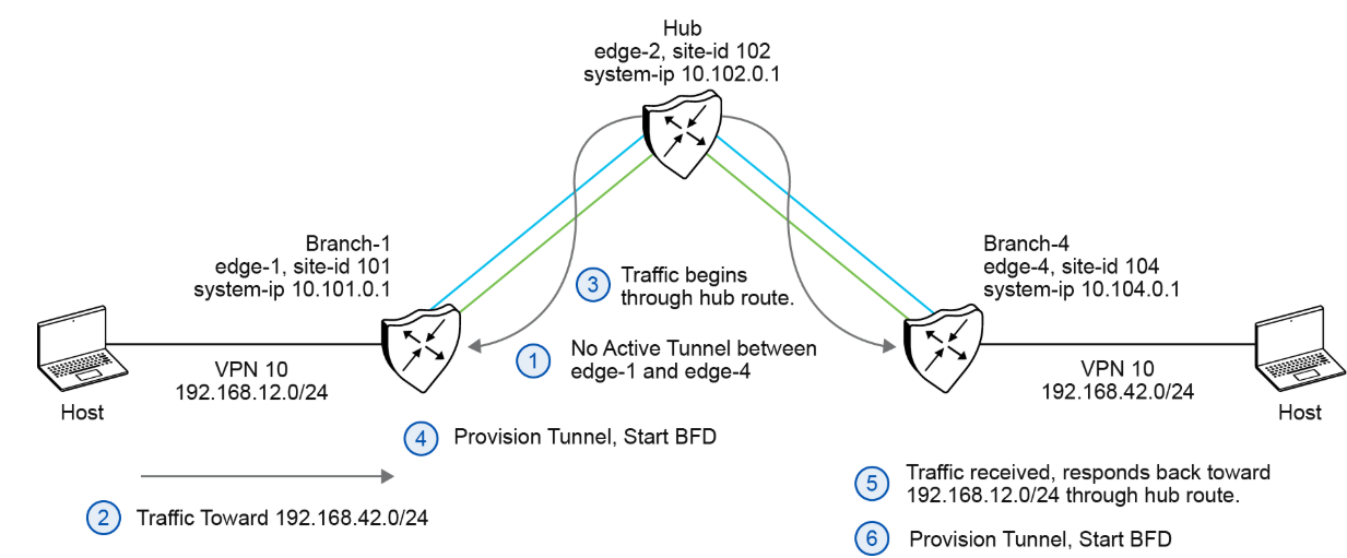
The figure shows the following steps that occur between two WAN Edge routers with an on-demand tunnel configured:
-
There is no active tunnel between the two WAN Edge routers. Both edge-1 and edge-4 are in Inactive state.
-
The host behind edge-1 initiates traffic toward the host behind edge-4.
-
The edge-1 device forwards the traffic through the backup path using the hub or backup node to edge-4.
-
The edge-1 device provisions the on-demand tunnel and begins BFD. The edge-4 device is now considered in active state on edge-1.
-
When the edge-4 device receives the return traffic destined for the host behind edge-1, it forwards the traffic through the backup path using the hub or backup node to edge-1.
-
The edge-4 device provisions the on-demand tunnel and begins BFD. The edge-1 device is now considered in active state on edge-4.
On-Demand Tunnel Mechanism in Detail—Tunnel is Active
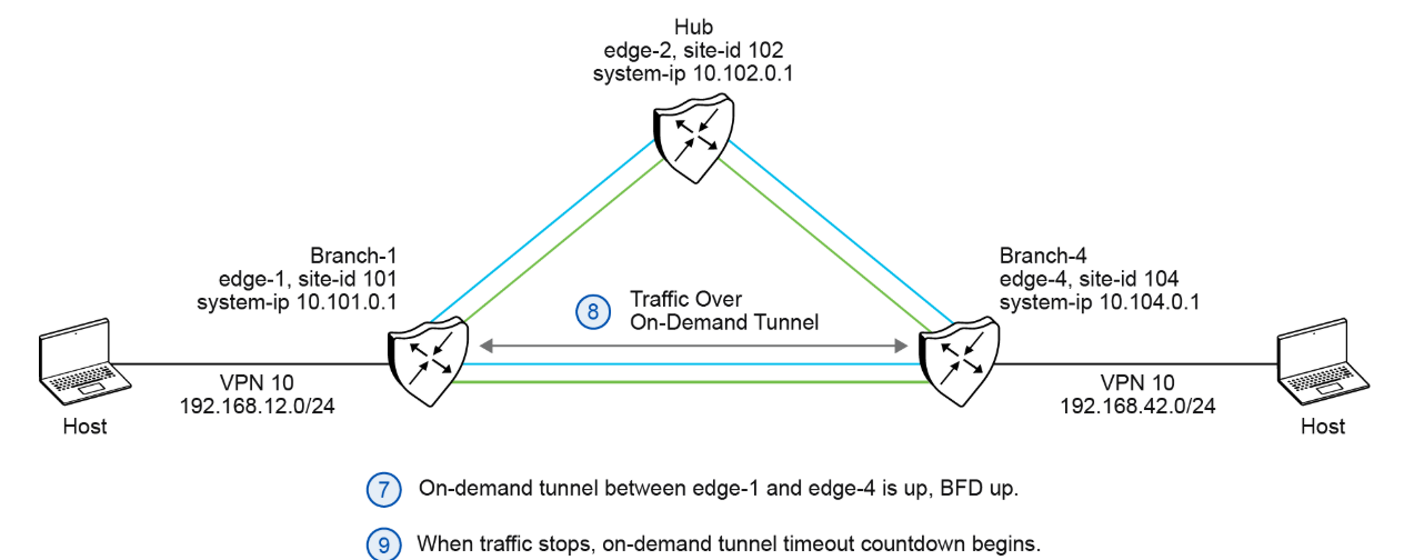
The figure shows that the traffic flow after the tunnel has been established between Branch-1 and Branch-4.
-
At this point, the on-demand tunnel between edge-1 and edge-4 is up, and BFD is up.
-
Traffic between the two WAN Edge devices takes the direct route through the on-demand tunnel.
-
Both edge-1 and edge-4 track the traffic activity on the on-demand tunnel in both directions.
If there is no traffic for the idle timeout duration, the on-demand tunnel is deleted, and the edge-1 and edge-4 devices return to the inactive state.

Comment
TABLE OF CONTENTS
- Onboarding & Provisioning Configuring Templates
- Authentication between vSmart & vBond
- Authentication between vSmart Controller
- Authentication between vBond & vEdge Router
- Authentication between vEdge Router & vManage NMS
- Authentication between vSmart Controller & vEdge Router
- Viptela Specific Port Terminology
- Deploy & Configure vManage & Generate Certificate
- Deploy & Configure vBond & Generate Certificate
- Deploy & Configure vSmart & Generate Certificate
- Configure vEdge & Generate Certificate
- SDWAN & NAT
- Secure DataPlane Bringup
- Enterprise CA for SDWAN Instances
- ZTP Process & PnP Overview
- Control Plane & Data Plane Operation - Unicast Routing Overview
- Configuring OMP & Its attributes
- Configure Unicast Overlay Routing
- Routing Configuration Example
- Segmentation Overview
- Configuring Segmentation
- Segmentation Configuration Example
- Data Traffic across Private WANs
- NAT in SDWAN & Data Encryption
- SD-WAN Viptela Policy Overview
- SD-WAN Centralized & Localized Control Policy Overview
- SD-WAN Centralized & Localized Data Policy
- Service Chaining
- Traffic Flow Monitoring
- vEdge Router as NAT Device
- Zone Based Firewalls
- Configure Centralized Control Policy
- Configuring Centralized Data Policy
- Configuring Cflowd Traffic Monitoring
- Configuring Zone based Firewall
- Service Chaining Configuration Example
- Configuring Service Side NAT
- Configuring Transport side NAT
- Control Policy Example 1: Hierarchical Topology
- Multi-Region Fabric
- Control Policy Example 2: Implementing Traffic Engineering
- Control Policy Example 2: Dynamic On-Demand Tunnels
- LAB Deploy Cisco SD-WAN Edge Routers
- LAB Deploy SDWAN Controllers
- LAB Deploy Cisco SD-WAN Devices Using Configuration Group
- LAB Implement Service-Side Routing Protocols
- LAB Implement TLOC Extensions
- LAB Implement Control Policies
- LAB Implement Data Policies
- LAB Implement Application-Aware Routing
- LAB Implement Branch and Regional Internet Breakouts
- LAB Migrate Branch Sites
RECENT POSTS
- Installing Context-Aware Network Access Control using Cisco ISE Policies
- Designing Network Access Control that is Scalable using Cisco ISE Architecture
- Enterprise Network Access Control and Policy Enforcement using Cisco ISE
- Secure Device Administration and Network Access Using AAA Architecture
- Designing Enterprise-Class Hybrid Cloud Connectivity Using AWS Networking Services
- Exploring Core AWS Networking and Messaging Concepts for Modern Cloud Architectures
- Understanding Key AWS Services for Modern Cloud Architectures
- Building a Strong AWS Foundation with Amazon S3, EC2, and Virtual Private Cloud
- Understanding the ENSDWI Course: Advanced Cisco SD-WAN (Viptela) Concepts
- A Complete Guide to the DCACI-A Course: Mastering Advanced Cisco ACI Concepts


LEAVE A COMMENT
Please login here to comment.