EMAIL SUPPORT
dclessons@dclessons.comLOCATION
USDeploy Configure vManage & Generate Certificate
vManage Installation Process
Follow these steps to install vManage:
- Obtain software and verify system requirements.
- Deploy the Open Virtualization Format (OVF) template.
- Perform the installation and initial configuration (hostname, NTP).
- Configure System-IP, Site-ID, and Organizational Name.
- If you use a local CA, install the root CA chain and resynchronize the vManage database.
Before commencing the vManage controller deployment, make sure that you size the VM accordingly with the overlay network design and scale. The more WAN Edge routers in your network, the larger your VM must be for deployment (virtual CPUs, RAM, and hard disk volumes). Solid State Drive (SSD) physical storage is required for normal vManage performance. You may need to allocate even more resources to a vManage VM when deploying vManage in multitenant mode. For better reliability and performance, consider deploying a cluster of three or more vManage controllers, in which case you must provision an extra vNIC in each VM dedicated for intra-cluster communications.
Deploy the OVF Template
To install the vManage OVF template follow these steps:
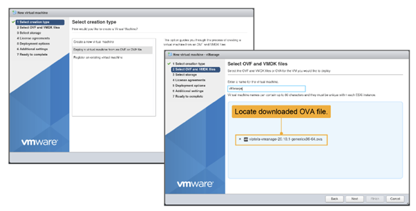
- In the ESXi web client, click Virtual Machines and choose the Create/Register VM option.
- Choose Deploy a virtual machine from an OVF or OVA file.
- Choose the OVA file in your storage (downloaded from the Cisco website) and provide a name for your VM.
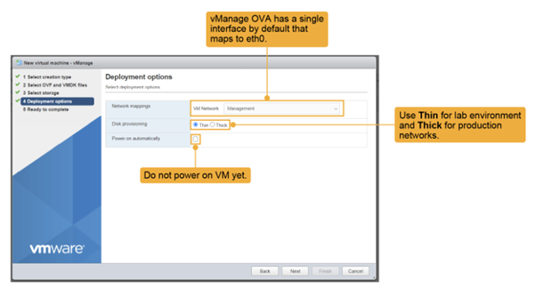
Choose Thick for a typical real-world deployment. For a lab environment, you can choose Thin. Do not power on the VM yet.
Choose the appropriate network mapping. For each VM (here, for vManage), you must virtually connect the VM to the corresponding LANs.
In the Network-Mapping GUI, choose the correct LAN to connect vNIC1. In this case, the correct LAN is the Management LAN (VPN 512). Double-check this step each time you do it. If you connect the VM to the wrong LAN, you will have connectivity issues later. Recall that, at this point, the VM has only one network interface enabled. You will edit the VM after it is deployed and add a second vNIC for VPN 0.
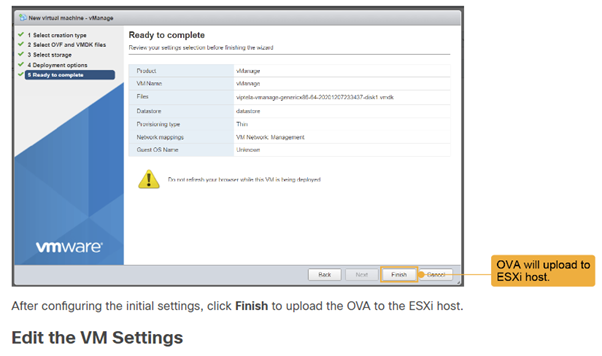
Choose Edit Setting option to make the chnages to the VM.
For the hard disk, click Add hard disk, set the disk size to 100 GB. This size is recommended for a lab environment. In a production environment, set the size according to the network requirements. Expand the New Hard disk and choose Thin or Thick provisioning. If deploying in a lab, use Thin.
The vManage database contains all configurations and operational data of the entire network (or networks, in the case of multitenant), and thus significant disk space is required for this database. The larger the database, the more information the vManage can collect and store over time, providing better telemetry and more useful network statistics.
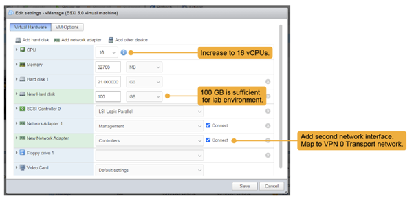
Click Add network adapter to add the additional Ethernet adapter.
Here, the second interface is placed in the Controllers LAN (for VPN 0 WAN transport connectivity). Recall that the first vNIC was assigned to the Management LAN (VPN 512).
Again, this process is the wiring up of the VM and must be done correctly to have connectivity.
Finally, depending on the available hardware resources, increase the number of CPUs assigned to vManage. In the figure, the number of assigned CPUs increased from 2 to 16.
Click Save and power on the VM.
After you deployed the VM instance, it will come up with factory default setting. But for minimum configuration, you should configure IP address of vBond orchestrator, vManage system IP address, tunnel Interface VPN 0 for exchanging control traffic among vBond, vManage, and vSmart devices.
vManage must be configured with following so that it can participate in overly network.
- Configure a tunnel interface (one interface) in VPN 0. This interface is one over which any WAN transport is connected and all Viptela devices must be able to access this interface. VPN 0 is the tunnel interface that carries all the control traffic among Viptela devices
- Enable OMP protocol if it is not enabled. This protocol is responsible for establishing and maintaining Viptela Control plane.
Perform a Database Installation
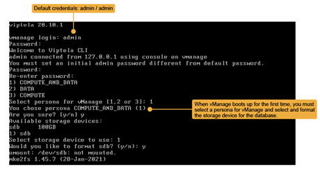
At the first boot of vManage, after you change the administrative password, you must choose the vManage persona and decide which of the available storage devices to use for the vManage database.
From vManage Release 20.6.1, each vManage server has a persona. The persona defines the role that the server has in a vManage cluster by determining which services run on the server.
vManage supports the following personas:
- Compute and Data: Includes all services that are required for vManage, including services that are used for the application, statistics, configuration, messaging, and coordination. This persona should be used for a standalone node, and for the first node in a vManage cluster.
- Compute: Includes services that are used for the application, configuration, messaging, and coordination. This persona does not include services that are used for statistics. A node with this persona cannot operate as a standalone node and must be part of a vManage cluster.
- Data: Includes only services that are used for the application and statistics. A node with this persona cannot operate as a standalone node and must be part of a vManage cluster.
When you decide which persona to configure for a server, be aware that a vManage cluster supports any of the following deployments of nodes:
- Three Compute and Data nodes
- Three Compute and Data nodes and three Data nodes
- Three Compute nodes and three Data nodes (supported only in an upgrade from an existing deployment)
For a single vManage deployment, select the first option, COMPUTE_AND_DATA as the persona. Then proceed to choosing the storage device that you set up in the previous step.
Before you can use it, you must format the new storage device. After that, vManage reboots and is ready for initial configuration.
Configure the vManage NMS with a Device Configuration Template
In order to configure the vManage NMS, a device configuration template must be created
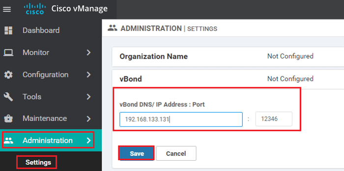
- Configure the address of the vBond orchestrator:
- Select the Administration section | Settings screen | Click the Edit button to the right of the vBond bar.
- In the vBond DNS/IP Address: Port field, enter the DNS name which points to the vBond orchestrator or the IP address of the vBond orchestrator and the port number to use to connect to it. | Click Save.
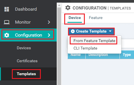
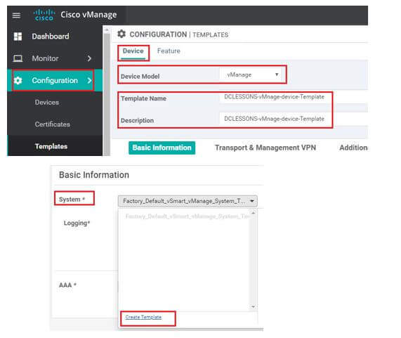
- In vManage NMS, select the Configuration | Templates screen. | In the Device tab, click Create Template | From the Create Template drop-down, select From Feature Template.
- From the Device Model drop-down, select vManage device and the required feature templates are shown with an asterisk (*), and the remaining templates are shown as optional. The factory-default template for each feature is selected by default
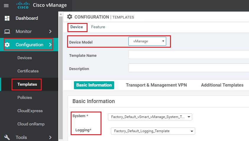
- In the Template Name field | name for the device template. This field is mandatory. In the Description field | enter a description for the device template. This field is mandatory.
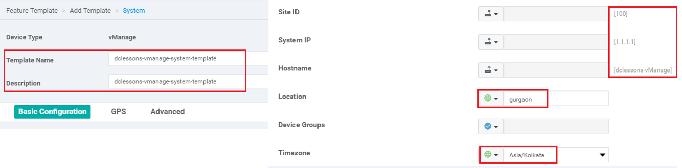
- In the System feature template | Site ID | System IP Address | Host name | Location | Time zone, and GPS Location.
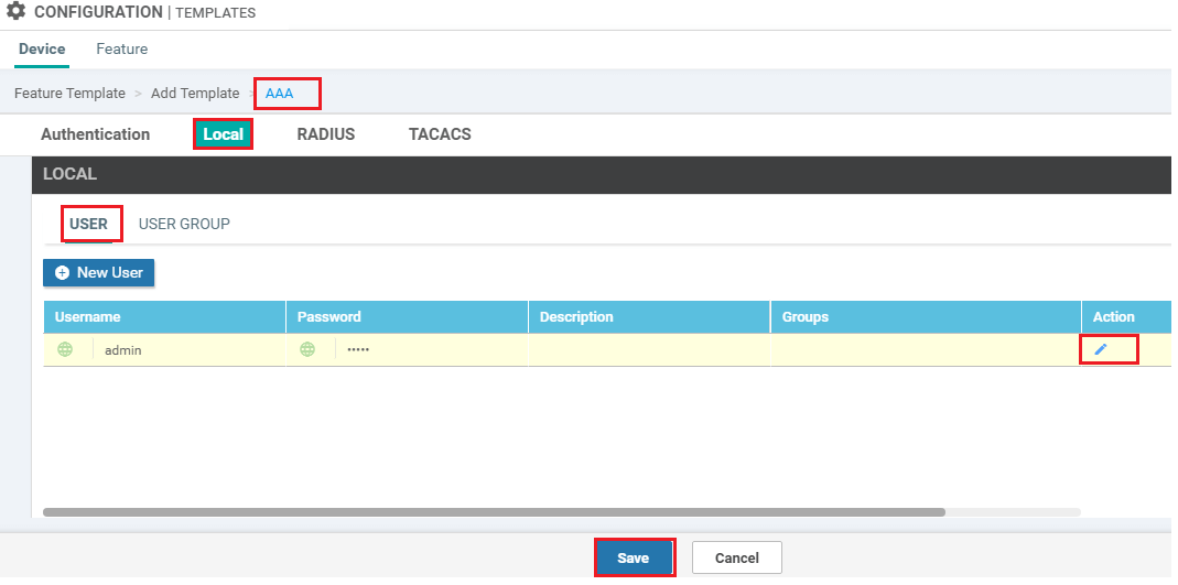
- In the AAA feature template | Local tab | click Users | change the password for the user "admin
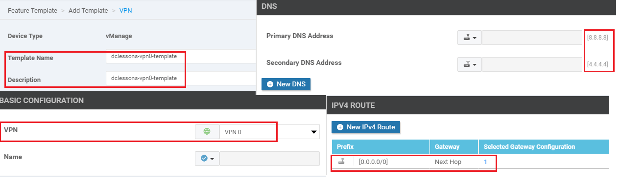
- In the VPN feature template | select VPN 0 | configure the system IP address and the address or host name of a DNS server. If necessary, click the Route tab | add a static route.
8. If you need to add a static route in VPN 512, in a second VPN feature template, select VPN 512, click the Route tab, and add the static route.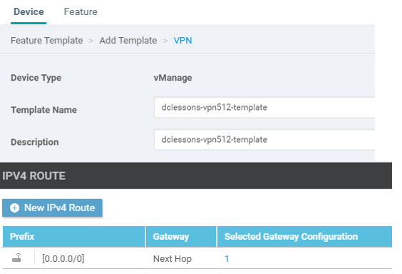
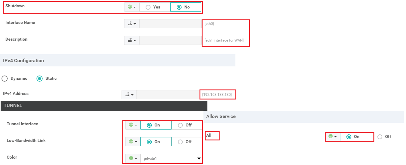
9. In the VPN-Interface-Ethernet feature template | configure the interface in VPN 0 to connect to the WAN transport network. In Shutdown | click No enter the Interface Name | Assign the interface either a dynamic or static address. In the Interface Tunnel tab, Tunnel Interface | click On.| assign a color to the Tunnel interface, | select the desired services to allow on the tunnel
10. In a second VPN-Interface-Ethernet feature template, configure management interface in VPN 512. In Shutdown | click No | enter the Interface Name | assign the interface either a dynamic or static Address.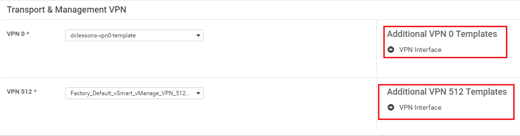
11. In the Security feature template | configure the control plane protocol
12. Optionally, modify the default Archive | Banner | Logging | NTP | SNMP feature templates.
13. Click Create. The new configuration template will be displayed in the Device Template table. The Feature Templates column shows the number of feature templates that are included in the device template, and the Type column shows "Feature" to indicate that the device template was created from a collection of feature templates.
14. In the Device Template table | locate the desired device template | Click the More Actions icon to the right of the row | select Attach Devices.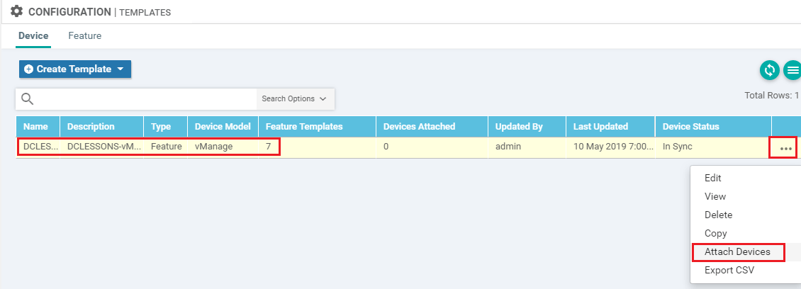
15. In the Attach Devices box, select the local vManage NMS from the Available Devices list | click the right- pointing arrow to move it to the Selected Devices box | Click Attach.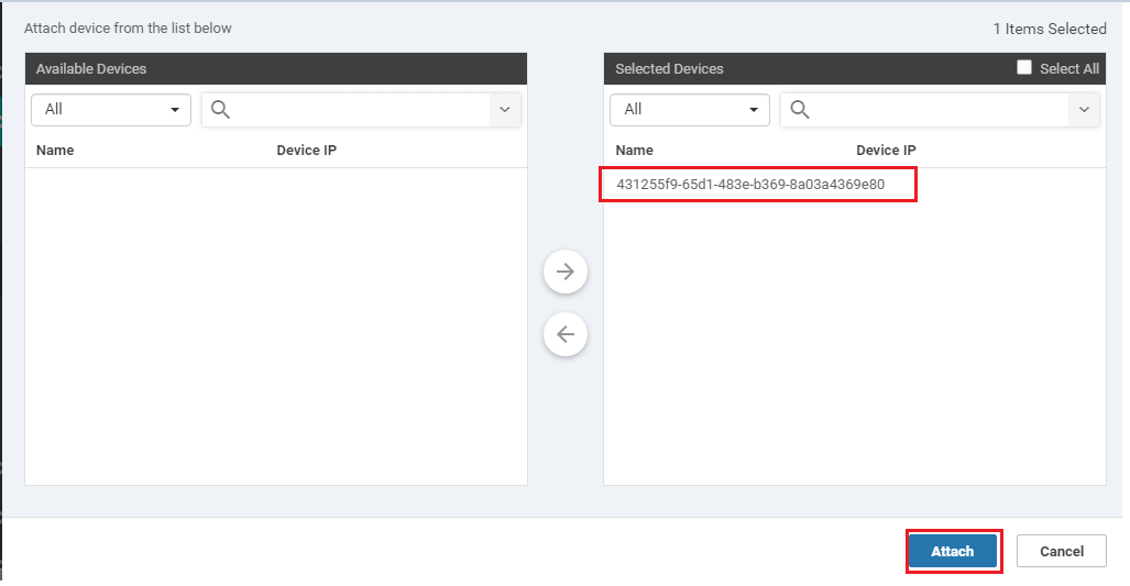
Sample CLI Configuration

Comment
TABLE OF CONTENTS
- Onboarding & Provisioning Configuring Templates
- Authentication between vSmart & vBond
- Authentication between vSmart Controller
- Authentication between vBond & vEdge Router
- Authentication between vEdge Router & vManage NMS
- Authentication between vSmart Controller & vEdge Router
- Viptela Specific Port Terminology
- Deploy & Configure vManage & Generate Certificate
- Deploy & Configure vBond & Generate Certificate
- Deploy & Configure vSmart & Generate Certificate
- Configure vEdge & Generate Certificate
- SDWAN & NAT
- Secure DataPlane Bringup
- Enterprise CA for SDWAN Instances
- ZTP Process & PnP Overview
- Control Plane & Data Plane Operation - Unicast Routing Overview
- Configuring OMP & Its attributes
- Configure Unicast Overlay Routing
- Routing Configuration Example
- Segmentation Overview
- Configuring Segmentation
- Segmentation Configuration Example
- Data Traffic across Private WANs
- NAT in SDWAN & Data Encryption
- SD-WAN Viptela Policy Overview
- SD-WAN Centralized & Localized Control Policy Overview
- SD-WAN Centralized & Localized Data Policy
- Service Chaining
- Traffic Flow Monitoring
- vEdge Router as NAT Device
- Zone Based Firewalls
- Configure Centralized Control Policy
- Configuring Centralized Data Policy
- Configuring Cflowd Traffic Monitoring
- Configuring Zone based Firewall
- Service Chaining Configuration Example
- Configuring Service Side NAT
- Configuring Transport side NAT
- Control Policy Example 1: Hierarchical Topology
- Multi-Region Fabric
- Control Policy Example 2: Implementing Traffic Engineering
- Control Policy Example 2: Dynamic On-Demand Tunnels
- LAB Deploy Cisco SD-WAN Edge Routers
- LAB Deploy SDWAN Controllers
- LAB Deploy Cisco SD-WAN Devices Using Configuration Group
- LAB Implement Service-Side Routing Protocols
- LAB Implement TLOC Extensions
- LAB Implement Control Policies
- LAB Implement Data Policies
- LAB Implement Application-Aware Routing
- LAB Implement Branch and Regional Internet Breakouts
- LAB Migrate Branch Sites
RECENT POSTS
- Installing Context-Aware Network Access Control using Cisco ISE Policies
- Designing Network Access Control that is Scalable using Cisco ISE Architecture
- Enterprise Network Access Control and Policy Enforcement using Cisco ISE
- Secure Device Administration and Network Access Using AAA Architecture
- Designing Enterprise-Class Hybrid Cloud Connectivity Using AWS Networking Services
- Exploring Core AWS Networking and Messaging Concepts for Modern Cloud Architectures
- Understanding Key AWS Services for Modern Cloud Architectures
- Building a Strong AWS Foundation with Amazon S3, EC2, and Virtual Private Cloud
- Understanding the ENSDWI Course: Advanced Cisco SD-WAN (Viptela) Concepts
- A Complete Guide to the DCACI-A Course: Mastering Advanced Cisco ACI Concepts


LEAVE A COMMENT
Please login here to comment.