EMAIL SUPPORT
dclessons@dclessons.comLOCATION
USVXLAN with Anycast RP and PIM
We know that L2VNI specific layer 2 BUM traffic is forwarded by following ways in VXLAN fabric:
- Via Underlay network Multicast routing
- Via Ingress-replication , in which copy of each ingress L2BUM frame is sent as unicast to every VTEP participating in same L2VNI.
In this chapter we will learn , VXLAN on PIM Multicast routing with Anycast-RP .
Below is the Topology used to explain the VXLAN on Multicast . Where Spine-11 and Spine-12 shares the Same Anycast-RP ( rendezvous Point ) IP address and belong to same Anycast-RP Set, that uses Loopback 200 IP.
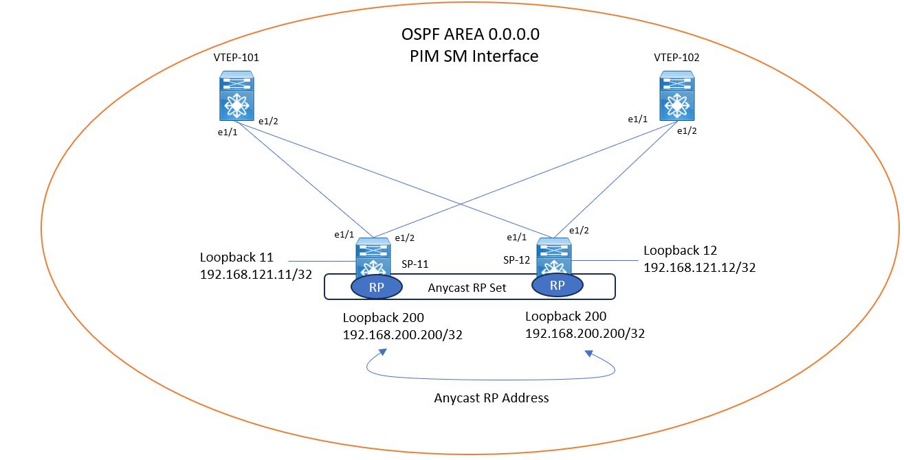
On both Spine ,additional loopback is also configured and are uses to identify as Anycast-RP group member. These Both IP address must be reachable from all switches.
Now Lets understand the configuration of Anycast-RP Multicast Routing Solution.
Step1: Configure Anycast-RP Cluster on both Spine Switches
- Enable PIM on both Spine Switches
- Configure Loopback 200 for Anycast-RP on both Switches
- Enable PIM and OSPF on these Interfaces.
feature pim ! interface loopback200 description ** Anycast-RP address ** ip address 192.168.200.200/32 ip router ospf UNDERLAY-NET area 0.0.0.0 ip pim sparse-mode
Step2: Assign Cluster Member IP and define Members on Spine Switches
- Configure Unique Cluster member IP for each Anycast-RP Cluster member.
- Enable PIM-SM and OSPF on it.
Configuration:
interface loopback11 description ** Unique Address for Anycast-RP ** ip address 192.168.121.11/32 ip router ospf UNDERLAY-NET area 0.0.0.0 ip pim sparse-mode ! ip pim anycast-rp 192.168.200.200 192.168.121.11 ip pim anycast-rp 192.168.200.200 192.168.121.12
Step3: Configure Group-Specific Rendezvous Point RP to all Switches
ip pim rp-address 192.168.200.200 group-list 224.0.0.0/4
Now below topology shows rest of the device configured IP address , which will be used in rest of the Topic.
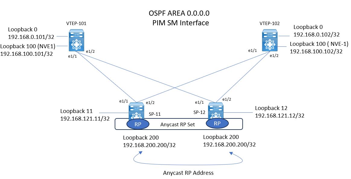
Once this all pre-requisite is done , your Anycast-RP configuration is nor ready and underlay network is capable of forwarding L2BUM Traffic.
Now lets configure the user VLAN , named VLAN 10 , which is attached to VNI 10000 on both of the VTEP . the Multicast Group 238.0.0.10 is also attached to VNI 10000 under NVE ( Network Virtualization Edge) interface. These configuration is to be done on both VTEP switches , VTEP-101 , VTEP-102.

Comment
TABLE OF CONTENTS
RECENT POSTS
- Installing Context-Aware Network Access Control using Cisco ISE Policies
- Designing Network Access Control that is Scalable using Cisco ISE Architecture
- Enterprise Network Access Control and Policy Enforcement using Cisco ISE
- Secure Device Administration and Network Access Using AAA Architecture
- Designing Enterprise-Class Hybrid Cloud Connectivity Using AWS Networking Services
- Exploring Core AWS Networking and Messaging Concepts for Modern Cloud Architectures
- Understanding Key AWS Services for Modern Cloud Architectures
- Building a Strong AWS Foundation with Amazon S3, EC2, and Virtual Private Cloud
- Understanding the ENSDWI Course: Advanced Cisco SD-WAN (Viptela) Concepts
- A Complete Guide to the DCACI-A Course: Mastering Advanced Cisco ACI Concepts


LEAVE A COMMENT
Please login here to comment.