EMAIL SUPPORT
dclessons@dclessons.comLOCATION
USBGP EVPN VXLAN Overview
In this example , we will start with understanding the configuration along with Intra-VNI Switching and then Inter-VNI Switching.
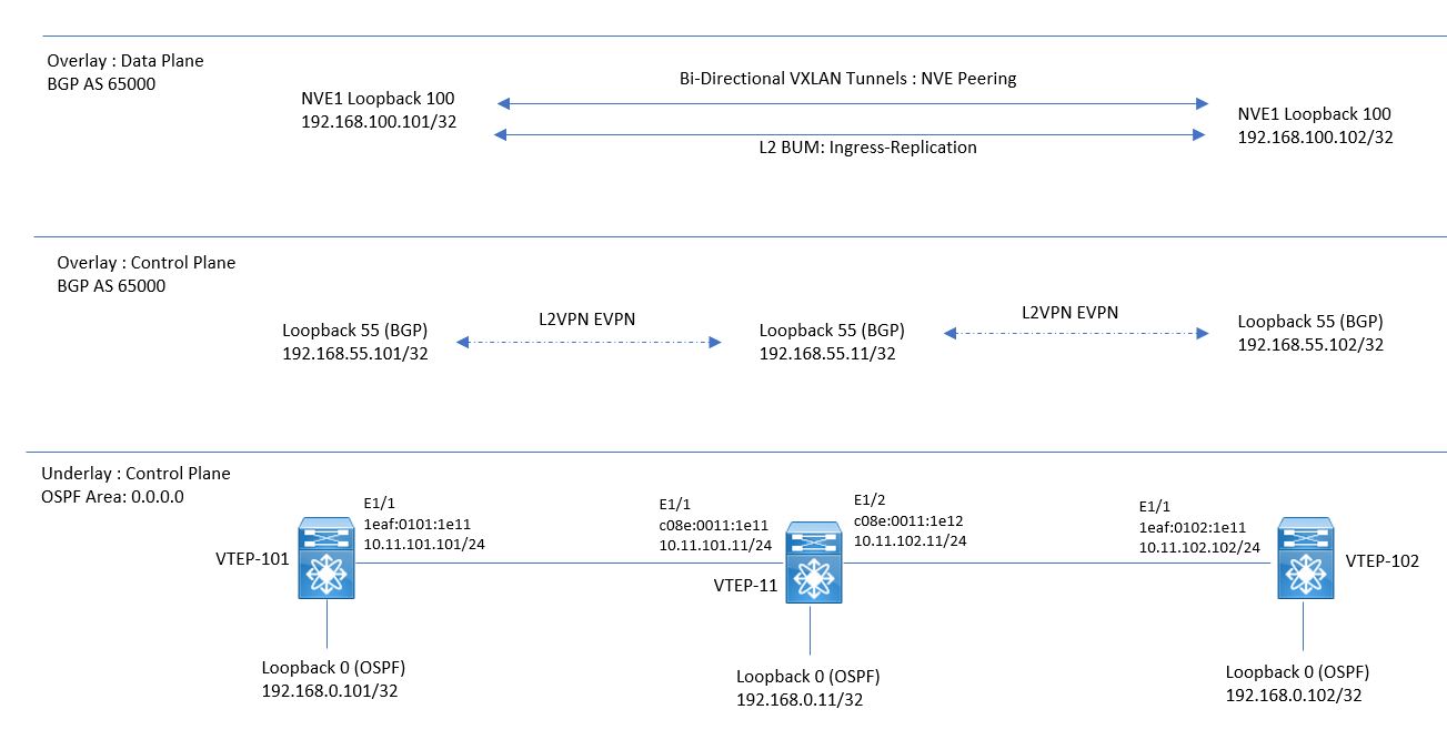
Refer the below topology which will be used as BGP EVPN VXLAN topology.
BGP EVPN VXLAN Configuration for Intra-VNI Switching
In this discussion , we are using the unicast-only routing , ( No Multicast support ) and using OSPF as IGP for Routing. This Underlay routing protocol has four main task from VXLAN point of view:
IP Connectivity between Loopback interfaces used for Overlay Network BGP peering
VTEP-101 and VTEP-102 will establish the iBGP L2VPN EVPN peering with Spine-11, using their loopback 55 interface. This Peering is used to exchange L2VPN EVPN NLRI. For this exchange VXLAN uses Route-type 3 “inclusive Multicast Route” , which will be used by leaf switches to introduce their willingness to participate in ingress-replication.
IP Connectivity between Loopback interfaces used for Overlay Network NVE peering
On Both VTEP , NVE Interfaces will establish the NVE peering between each other using Loopback Interface 100. The NVE Interface are used for:
- For VXLAN Encapsulation and decapsulation data traffic
- For Advertisement of MAC address using MAC advertisement Route as L2VPN EVPN BGP update.
Advertise all Inter-Switch Link subnets
OSPF will advertise the Inter-Switch Link IP address , which has to be reachable to all switches for next-hop resolving
Advertise Multicast RP IP address
In the scenario , where Multicast is used for L2BUM traffic , Multicast routing has to be enabled in underlay network. The RP of each Multicast group must be reachable from all switches in local VXLAN fabric.
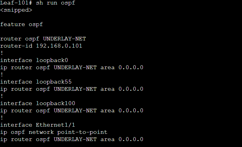
Build Underlay Network: OSPF Configuration
In order to configure OSPF , we have enable OSPF feature and start the OSPF process and define the OSPF Router-ID.
Below is the configuration used for OSPF on leaf-101.
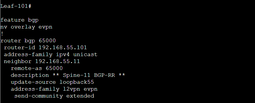
Build Overlay Network: BGP L2VPN EVPN Configuration
Once BGP configuration is done , VTEP-11 will be iBGP neighbor with VTEP-101 and VTEP-102. VTEP-101 will exchange BGP L2VPN EVPN updates. The “nv overlay evpn” command is required before BGP neighbor is specified as an L2VPN EVPN peer.
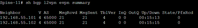
Once BGP configuration is done on Leaf switches , VTEP-11 ( Spine) will also follow the same configuration with an exception that Leaf-101/102 are defined as route-reflector clients.
Below output shows that VTEP-11 (Spine) has formed iBGP L2VPN EVPN peering with both VTEP-101/102 , but neither switch has sent any BGP Updates.
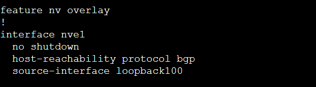
Build NVE Peering (Part of Build Overlay Network )
Use feature “nv overlay”, in order to configure NVE interface. Host reachability information will be exchanged by BGP using NVE Interface, that is loopback 100 as Source IP address. These NVE interface are only needed on both Leaf Switches only.
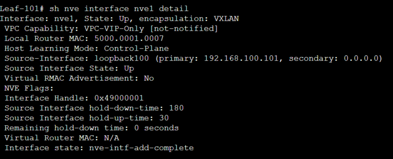
Below figure explains that NVE interface is UP and it is using IP address 192.168.100.101 as source IP address.
Configure Host Mobility Manager (Part of Build Overlay Network)
In NX-OS , VXLAN service has a feature called Host Mobility manager , which keeps track of MAC address moving inside VXLAN fabric switches.
Configure Anycast Gateway (Part of Build Overlay Network)
VM can move from one leaf to another leaf in VXLAN fabric. Due to which it is required to configure VLAN Specific SVI on every leaf switches where the VLAN Exists. Each SVI will use the same anycast MAC-address regardless of L3 SVI.
“feature fabric forwarding”
Configure VLAN based Service (Part of Build Overlay Network)
Configure VLAN based Virtual Network segment ( VN-Segment) on each switches
feature vn-segment-vlan-based
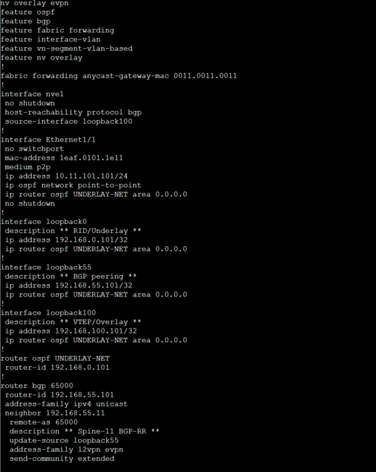
Complete VXLAN service configuration on Leaf-101
Below figure summarizes the VXLAN configuration required for Switches before layer 2 Intra-VNI or layer 3 Inter VNI service can be implemented in to VXLAN fabric.
Now Once Overly Build is ready , we will start configuring Intra-VNI Service
Configure Intra-VNI Service ( L2VNI) in VXLAN
In order to configure Intra-VNI , configure L2 VLAN and attach it to VN-Segment. Here VLAN 10 is attached to VNI 10000.
vlan 10 name VLAN10-mapped-to-VNI10000 vn-segment 10000
Now once this is done , we will configure EVPN instance for VNI 10000 , where RD and RT value will be used to differentiate possible Overlapping MAC address in different VNI.
How RD and RT is derived , based on below formula :
RD = BGP Router ID: Base value 32767+VLAN ID
Example : Leaf-101 has router ID 192.168.55.101 then RD = 192.168.55.101:32777 for all MAC address participating in VLAN 10/VNI10000.
Now RT is used to export MAC advertisement route , whose value is created based on below Formula :
RT = BGP AS : VNI-ID : RT=65000:10000
RT is same in all leaf switches where VLAN 10 is used for VNI 10000. Note that VLAN ID need not to be same in all VTEP Switches , as VLAN ID has only local switch significance where as VNI-ID has fabric wide Significance.

Comment
TABLE OF CONTENTS
RECENT POSTS
- Installing Context-Aware Network Access Control using Cisco ISE Policies
- Designing Network Access Control that is Scalable using Cisco ISE Architecture
- Enterprise Network Access Control and Policy Enforcement using Cisco ISE
- Secure Device Administration and Network Access Using AAA Architecture
- Designing Enterprise-Class Hybrid Cloud Connectivity Using AWS Networking Services
- Exploring Core AWS Networking and Messaging Concepts for Modern Cloud Architectures
- Understanding Key AWS Services for Modern Cloud Architectures
- Building a Strong AWS Foundation with Amazon S3, EC2, and Virtual Private Cloud
- Understanding the ENSDWI Course: Advanced Cisco SD-WAN (Viptela) Concepts
- A Complete Guide to the DCACI-A Course: Mastering Advanced Cisco ACI Concepts


LEAVE A COMMENT
Please login here to comment.