EMAIL SUPPORT
dclessons@dclessons.comLOCATION
USLAB Deploy Multi-Pod Fabric
Task:
- Extend the existing fabric by adding a second Pod consisting of a spine and a leaf switch
- Attach an endpoint to the leaf in the second pod and examine traffic flows between the pods.
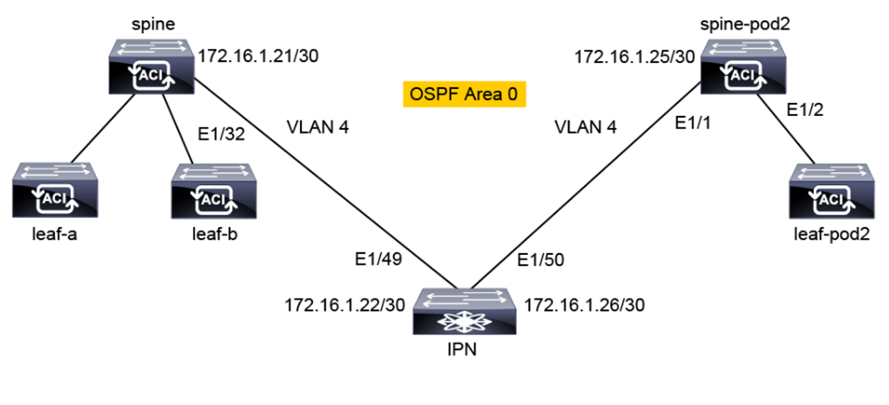
Topology:
Solution:
Use PuTTY to connect to the external Cisco Nexus switch and verify the LLDP neighbors.
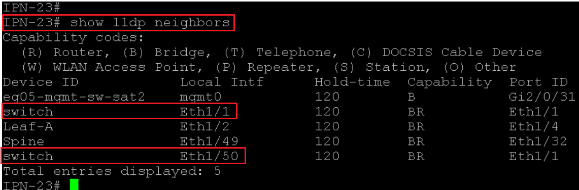
The two switches in pod 2 should appear with the default switch name, as they have not yet been discovered and registered. The node connected to Eth1/49 is pod-1 spine. The pod-2 spine is attached to Eth1/50 and the pod-2 leaf is attached to Eth1/1.
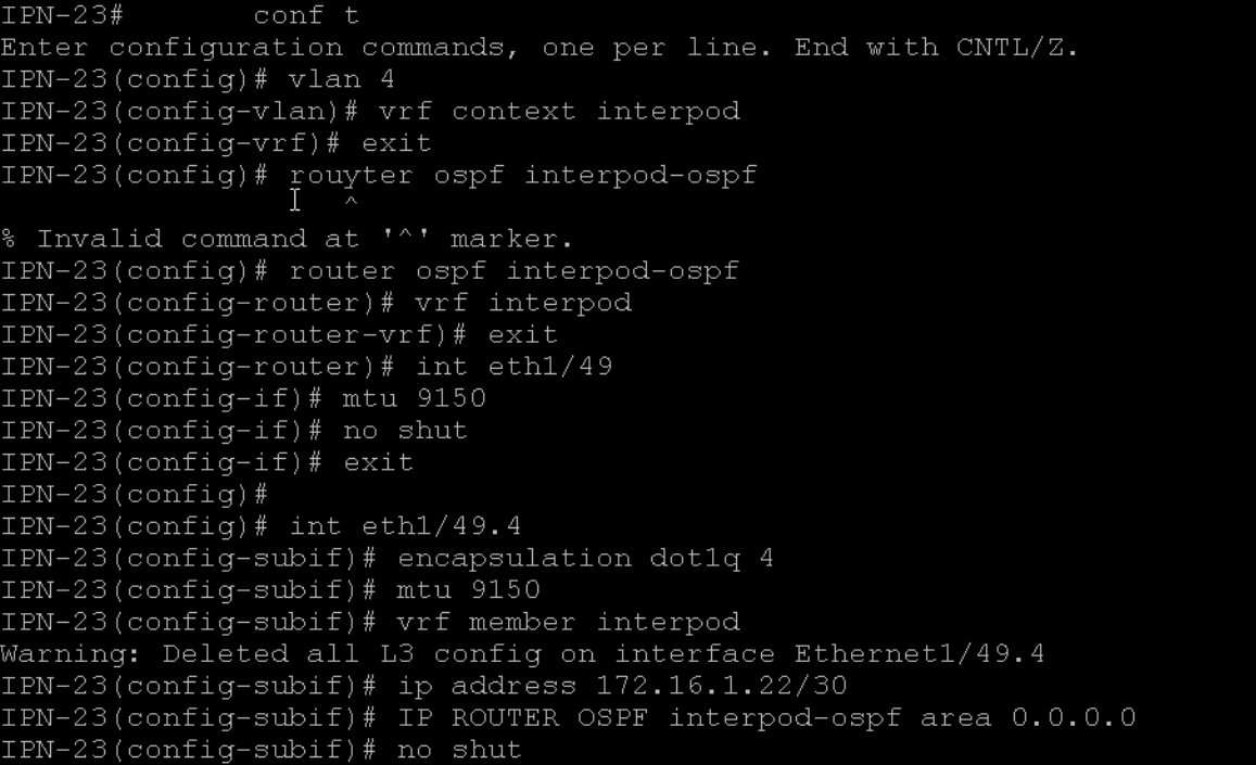
On the IPN, configure the following items for OSPF connectivity to the spine in the seed pod:
-
VLAN 4. This VLAN ID is a fixed ID used by the configuration wizard in the APIC user interface to establish IPN connectivity.
-
VRF interpod. Although not mandatory for inter-pod (IPN) communication, it is recommended for traffic segregation.
-
OSPF process interpod-ospf. The VRF and OSPF process names have only local significance.
-
MTU 9150 on Ethernet 1/49. This MTU is a default value configured by the wizard in the APIC user interface. Eth1/49 is connected to the spine.
-
Routed subinterface Eth1/49.4 for VLAN ID 4 with these parameters:
-
MTU 9150
-
Member of VRF interpod.
-
IP address 172.16.1.22/30
-
Member of the OSPF backbone area
-
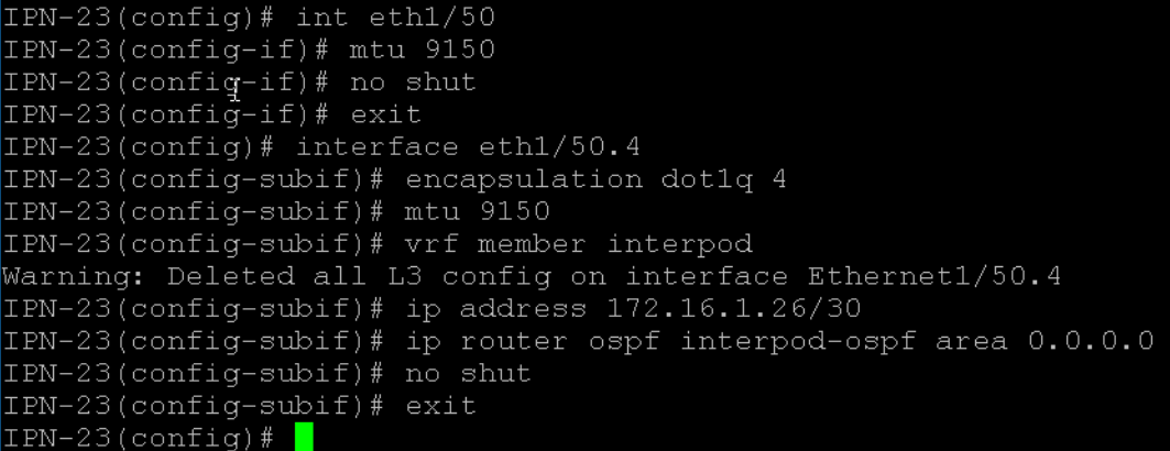
On IPN, enable OSPF connectivity to the second pod spine using the following parameters:
-
MTU 9150 on Ethernet 1/50.
-
Routed subinterface Eth1/50.4 for VLAN ID 4 with these parameters:
-
MTU 9150
-
Member of VRF interpod
-
IP address 172.16.1.26/30
-
Member of the OSPF process interpod-ospf and backbone area
-
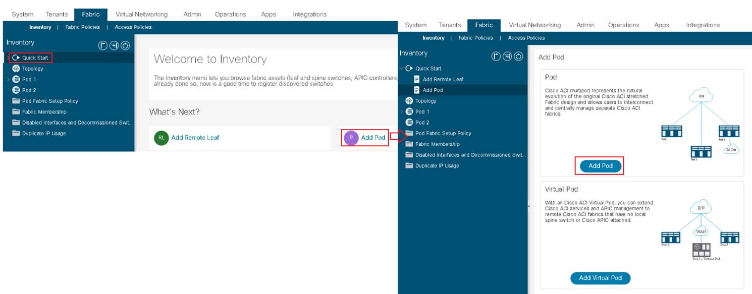
Go to Fabric > Inventory > Quick Start > Add Pod and choose Add Pod
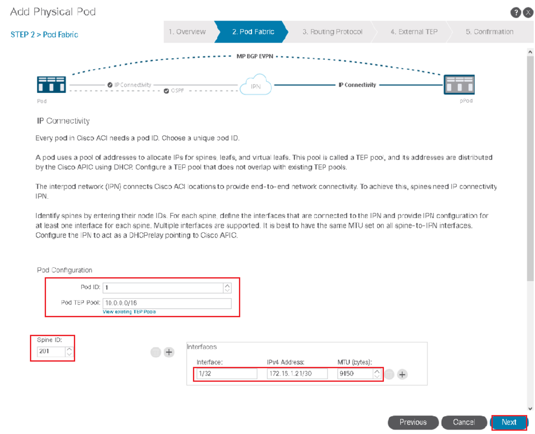
In IP Connectivity, enter the following parameters and click Next:
-
Spine ID: 201
-
Interface: 1/32 (spine interface connected to IPN)
-
IP address: 172.16.1.21/30
-
MTU (bytes): 9150
These parameters define the IP settings of the peer link to the IPN.
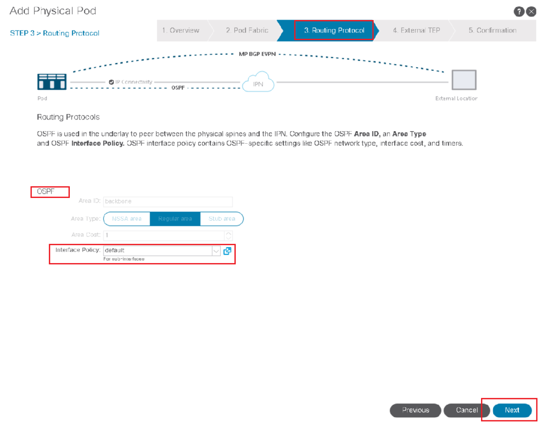
In Routing Protocol, choose the interface policy default and click Next.
In External TEP, configure the following values and click Next:
-
External TEP Pool: 192.168.1.0/24 (Keep the default auto-filled value). Caution - if you enter this address instead of keeping the auto-filled value, the wizard will return an error and you will have to repeat the procedure. Leave the auto-filled address unchanged.
-
Data Plane TEP IP: 192.168.90.1/32 (BGP next-hop for networks advertised by the seed pod to other pods)
-
Router ID: 10.4.4.4
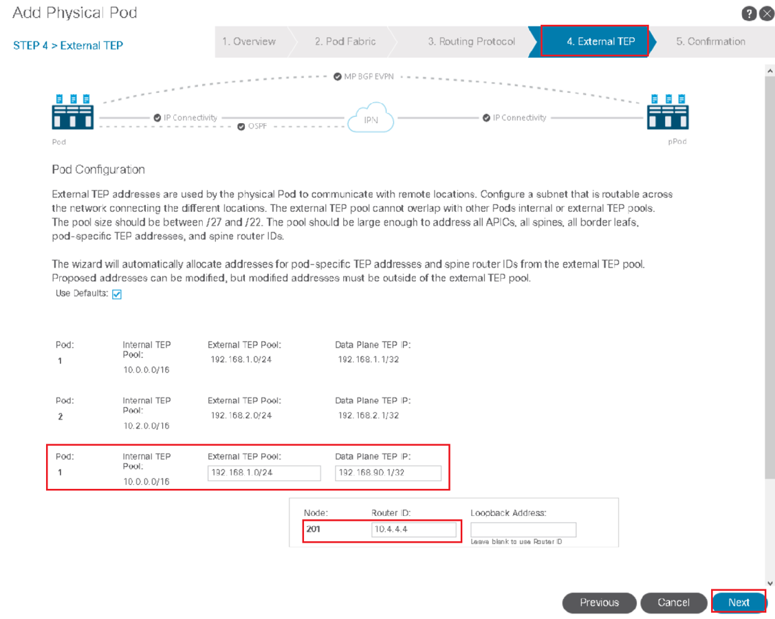
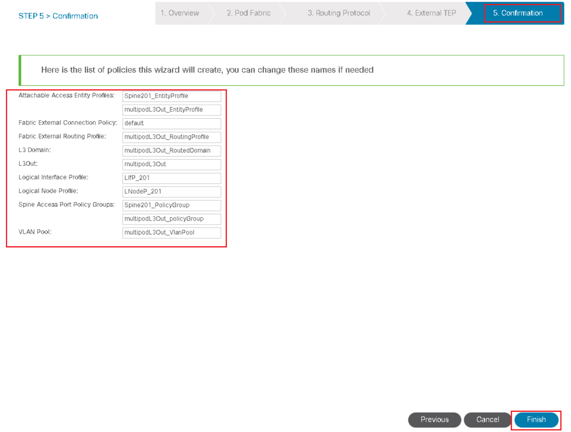
Review the objects that will be created by the wizard and click Finish.
Review the summary page that informs you about the APIC web server restart. You may briefly see an error. Do not proceed with the configuration of the physical pod yet.
You will need to refresh the browser to connect to the APIC.

Comment
TABLE OF CONTENTS
RECENT POSTS
- Installing Context-Aware Network Access Control using Cisco ISE Policies
- Designing Network Access Control that is Scalable using Cisco ISE Architecture
- Enterprise Network Access Control and Policy Enforcement using Cisco ISE
- Secure Device Administration and Network Access Using AAA Architecture
- Designing Enterprise-Class Hybrid Cloud Connectivity Using AWS Networking Services
- Exploring Core AWS Networking and Messaging Concepts for Modern Cloud Architectures
- Understanding Key AWS Services for Modern Cloud Architectures
- Building a Strong AWS Foundation with Amazon S3, EC2, and Virtual Private Cloud
- Understanding the ENSDWI Course: Advanced Cisco SD-WAN (Viptela) Concepts
- A Complete Guide to the DCACI-A Course: Mastering Advanced Cisco ACI Concepts


LEAVE A COMMENT
Please login here to comment.