EMAIL SUPPORT
dclessons@dclessons.comLOCATION
USNSX Logical Switch Packet Flow
Logical Switch Packet Walk:
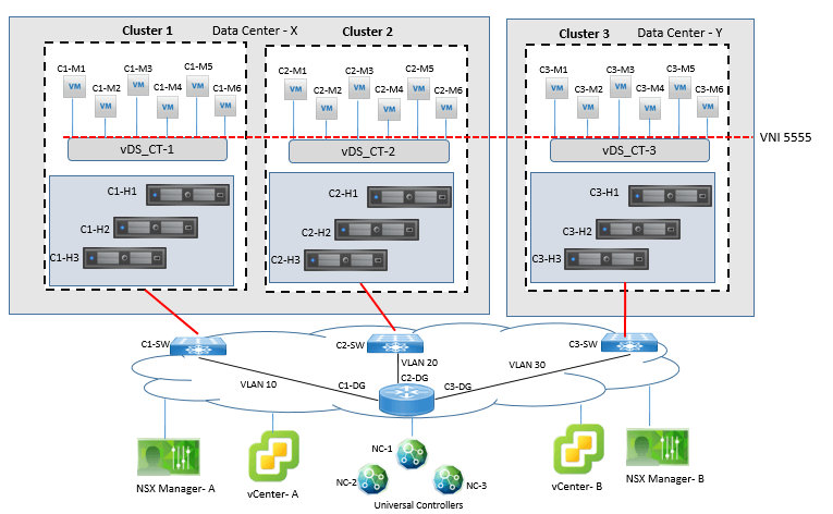
For each packet walk, it uses Universal Logical switch 5555 as broadcast domain. Below topology is used for each sections of packet walk. Each ESXi cluster has three ESXi host and each ESXi host has two VM powered ON.
- Cluster 1 VXLAN encapsulation will be on VLAN 10 in DC X
- Cluster 2 VXLAN encapsulation will be on VLAN 20 in DC X
- Cluster 3 VXLAN encapsulation will be on VLAN 30 in DC Y
IP addressing of each ESXi host and it’s connected VM is shown and presented well in dig.
Example 1: Logical Switch packet Walk
In this example, let’s assume that C1-M1 is sending frame to VM C1-M2 and assume the following to be true before packet walk:
- C1-M1 and C1-M2 are powered ON and connected to Universal logical switch 5555.
- C1-M1 and C1-M2 are using MAC address from their respective vmx file
- Logical switch 5555 is configured for MAC address learning
- NSX Universal Controller NC-2 has been given responsibility for VNI 5555
- C1-M1 knows the MAC address of C1-M2
Step1: C1-M1 will send frame with source IP C1-M1-IP with destination IP is C1-M2-IP, it will use Source MAC of C1-M1-MAC, and destination MAC of C1-M2-MAC.
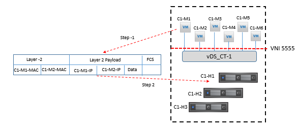
Step 2. Logical Switch 5555 in ESXi host C1-H1 will receive the frame from C1-M1 VM and capture the source MAC address, C1-M1-MAC.
Step 3. As source MAC address C1-M1-MAC is the same MAC address present in the vmx file of C1-M1, and it is already present in the MAC table of logical switch 5555 of C1-H1 the logical switch will now check for destination MAC address of the frame.
Step 4. Now destination MAC address C1-M2-MAC is the same MAC address present in the vmx file of VM C1-M2, and the MAC address is already in logical switch 5555 MAC table in C1-H1
Step 5. Logical switch 5555 in C1-H1 delivers the frame to C1-M2.
Example 2: Logical Switch packet Walk
In this example, let’s assume that C1-M1 is sending frame to VM C1-M2 and assume the following to be true before packet walk:
- C1-M1 and C1-M2 are powered ON and connected to Universal logical switch 5555.
- C1-M1 and C1-M2 are using MAC address not from their respective vmx file
- Logical switch 5555 is configured for MAC address learning
- NSX Universal Controller NC-2 has been given responsibility for VNI 5555
- C1-M1 knows the MAC address of C1-M2
Step 1. C1-M1 will send a frame with the source IP of C1-M1-IP, and destination IP of C1-M2-IP, It will use Source MAC of C1-M1-MAC, along with destination MAC of C1-M2-MAC.
Step 2. Logical Switch 5555 in ESXi host C1-H1 receives the frame from C1-M1 VM and will capture the source MAC address, C1-M1-MAC.
- If the MAC address is not in present in its MAC table, logical switch 5555 in C1-H1 will add this Source MAC information in its MAC table and will also inform to the NSX Controller NC-2 if theReplication Mode configured for the logical switch is Unicast or Hybrid.
- If the MAC address is present in the MAC table of logical switch 5555 in C1-H1 but it find that it belongs to a different virtual machine in C1-H1 host, it will update its MAC table and not inform to NC-2.
- If the MAC address is present in the MAC table of logical switch 5555 in C1-H1 but it finds that it belong to a different virtual machine in a VTEP but different from C1-H1, it will update its MAC address table and will inform to NC-2 if the Replication Mode for the logical switch is configured Unicast or Hybrid.
In all above each case a copy of the MAC address will also be sent to the Switch Security module. If C1-M1 is using an 802.1Q tab, the VLAN number will also be provided to the Switch Security module; else the VLAN number provided to the Switch Security module is 0.
Step 3. Logical switch 5555 in C1-H1 captures the destination MAC address C1-M2-MAC from Source Packet.
Now if the destination MAC address is not present in the MAC table of logical switch 5555 in C1-H1, the logical switch 5555 will sent query to NC-2 for the destination MAC address if the Replication Mode for the logical switch is configured as Unicast or Hybrid. If C1-H1 host does not receive any response from NC-2, or if NC-2 is down, or if the Replication Mode is configured as Multicast, the logical switch will replicate the frame.
In this case, since the MAC C1-M2-MAC is local to C1-M2, it is expected and true that NC-2 will not have an entry for this MAC address.
Step 4. After following step 3, logical switch 5555 in C1-H1 forwards the frame to C1-M2.
- After receipt C1-M2 replies back to C1-M1 with source MAC address C1-M2-MAC, logical switch 5555 in C1-H1 will learn this MAC address, as explained in step 2a.
Example 3: Logical Switch packet Walk
In this example Virtual Machine C1-M3 sends a frame to Virtual Machine C2-M4. Now let’s assume the following to be true:

Comment
TABLE OF CONTENTS
- LAB NSX Manager Installation
- LAB NSX Logical Switching Configuration
- LAB NSX Logical Router Configuration
- LAB NSX EDGE SERVICES GATEWAY
- Gateway
- LAB NSX Edge Service Gateway as DHCP Relay
- LAB NSX Configuring L2VPN
- LAB NSX DFW Configuration
- LAB NSX Dynamic Security Group Configuration
- LAB NSX Micro-Segmentation
RECENT POSTS
- Installing Context-Aware Network Access Control using Cisco ISE Policies
- Designing Network Access Control that is Scalable using Cisco ISE Architecture
- Enterprise Network Access Control and Policy Enforcement using Cisco ISE
- Secure Device Administration and Network Access Using AAA Architecture
- Designing Enterprise-Class Hybrid Cloud Connectivity Using AWS Networking Services
- Exploring Core AWS Networking and Messaging Concepts for Modern Cloud Architectures
- Understanding Key AWS Services for Modern Cloud Architectures
- Building a Strong AWS Foundation with Amazon S3, EC2, and Virtual Private Cloud
- Understanding the ENSDWI Course: Advanced Cisco SD-WAN (Viptela) Concepts
- A Complete Guide to the DCACI-A Course: Mastering Advanced Cisco ACI Concepts


LEAVE A COMMENT
Please login here to comment.