EMAIL SUPPORT
dclessons@dclessons.comLOCATION
USVerifying Cisco APIC Cluster
Once the Cisco ACI fabric prerequisites are met, such as correct cabling and connections, you can configure the APIC to start the discovery and initialization process. Although discovery is automated, you should be prepared to troubleshoot issues. For example, discovery may fail if the APICs and switches have mismatched time and date settings, or if LLDP information is not exchanged. Problems can also occur in the APIC cluster, so verifying both the discovery process and the cluster is important.
Fabric Discovery Process
The APIC cluster provides DHCP, bootstrap configuration, and image management to automate startup and upgrades. The bootstrap sequence begins when switches boot with ACI images. Cisco Nexus 9000 switches and APICs use a reserved overlay for the boot process. This infrastructure space is hardcoded on the switches and allows the APIC to connect to a leaf through the default overlay.
The infrastructure space is securely isolated and used for topology discovery, management, and addressing. Communication within the fabric happens through internal private IP addresses, enabling APICs to talk to fabric nodes and other APICs in the cluster. APICs discover each other’s IP addresses and node information using LLDP.
APIC Cluster Discovery Process
- Each APIC uses internal private IPs to communicate with nodes and other APICs. Discovery of other APICs happens via LLDP.
- APICs maintain an appliance vector (AV), which maps APIC IDs to IP addresses and UUIDs. Initially, each APIC only knows its own IP, while others are marked unknown.
- When a switch reboots, it receives the AV from the APIC via LLDP, advertises it to neighbors, and reports differences back to APICs.
Through this process, APICs learn about other controllers via switches. Once validated, APICs update their AVs and program switches with the new information. Switches then advertise the updated AV until all devices share the same AV and all APICs know each other’s IP addresses.
Discovery Stages
Fabric discovery happens in three stages:
- The leaf directly connected to the APIC is discovered.
- Spines connected to that leaf are discovered.
- Other leaf nodes and APICs in the cluster are discovered.
During this process, a node is considered active when it can exchange heartbeats with the APIC using SSL-encrypted TCP communication (intra-fabric messaging). This same process is used by the APIC to push policies to leaf nodes. LLDP and IS-IS convergence occur in parallel, while DHCP assigns infrastructure VTEP addresses and optionally installs firmware on switches. A minimal bootstrap configuration must be done on the first APIC before automated discovery begins.
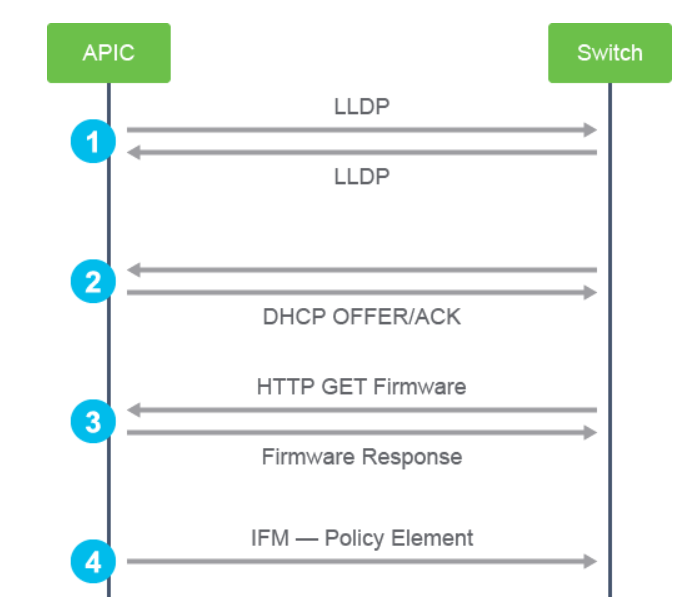
The steps are:
- LLDP neighbor discovery
- TEP IP address assignment to the node
- Node software upgraded if necessary
- Policy element IFM setup
Once the first APIC (APIC1) is set up, you can access the Cisco APIC GUI using a web browser. The Cisco APIC GUI runs HTML5 and eliminates the need for Java to be installed locally. Then you need to register the switches. When switches connected to other APICs are finally registered, the other APICs are discovered and join the APIC cluster.
Node status may fluctuate between several states during the fabric registration process. The states are shown in the fabric node vector table. The Cisco APIC CLI acidiag fnvread command that shows the fabric node vector table and sample output are provided further in this section. The following describes each state:
- Unknown: Node is discovered but no node ID policy is configured.
- Undiscovered: Node ID is configured but not yet discovered.
- Discovering: Node is discovered but IP is not yet assigned.
- Unsupported: Node is not a supported model.
- Disabled: Node has been decommissioned.
- Inactive: No IP connectivity.
- Active: Node is active.
Leaf CLI Verification
The show lldp neighbors command from the leaf is essential in determining whether an APIC LLDP is coming from the APIC operating system or the VIC. This example shows example outputs of this command.
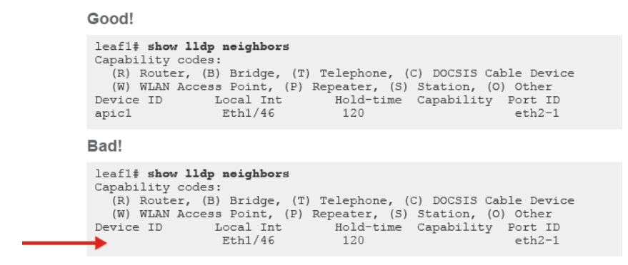
If there is an entry but the Device ID is not showing the hostname of the Cisco APIC, the Virtual Interface Card (VIC) may be configured with LLDP enabled.
Unique TEP Range for the Infrastructure
When setting up the fabric through the APIC, you must define tunnel endpoint (TEP) addresses (for example, 10.0.0.0/16) for the infrastructure VRF used for internal communication. This subnet is not exposed to the legacy network. It is recommended to assign an unused subnet between /16 and /21. The size of the subnet affects the scale of the pod, and most customers use an unused /16.
A unique, network-wide TEP IP address is required because the Cisco APIC does not use VRFs.
Cisco APIC provides redundancy at multiple levels:
- Interface-level redundancy: APICs use bonded interfaces, typically dual-homed to two leaf switches.
- Cluster-level redundancy: Multiple APIC nodes form a cluster.
There are two bonded interfaces:
- Bond0: Connects to the fabric (infra and in-band connections to leaf switches).
- Recommended to connect to two separate leaf switches.
- No IP address is assigned to Bond0.
- bond0.infra VLAN: This subinterface connects to the leaf switch. The VLAN ID is specified during initial APIC setup. It receives a dynamic IP address from the TEP pool defined during configuration.
- Bond1: Connects to the out-of-band (OOB) management segment.
- No IP address is assigned to Bond1.
- oobmgmt: This interface is created from Bond1 and allows management access to the APIC. Its IP address is assigned during the initial APIC configuration.
The APIC routing table shows connectivity for infra and OOB management. The APIC does not use VRFs. Traffic sourced from the APIC within the TEP pool is directed to the infra tenant. For example, the gateway for the 10.0.0.0/16 route (TEP pool) points to 10.0.0.30 in the infra tenant.
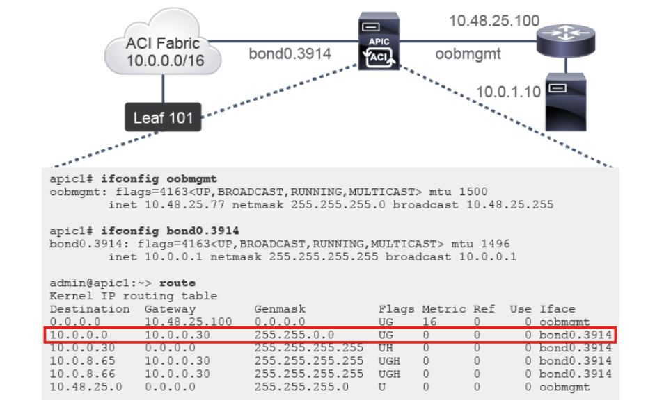
In this example, 10.48.25.0/24 is chosen for the OOB network, while the 10.48.25.100 IP address on the router interface toward the Cisco APIC is the default gateway for the APIC oobmgmt interface. The diagram illustrates a circumstance where an overlapping IP address range exists on the external router. Therefore, a syslog or Microsoft Active Directory (AD) server with an IP address 10.0.1.10 will not be reachable from the Cisco APIC, because it overlaps with the TEP-defined pool range.
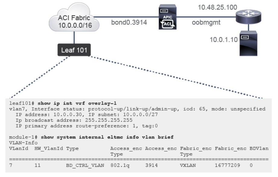
You can perform verification on the leaf switch as well, and see that the 10.0.0.30/32 is acting as gateway for the Cisco APIC route in the infrastructure. Also, you can see that it is mapping access encap 3914 to platform-independent VLAN 7.
Check Which bond0 Uplink Is Active on Cisco APIC
The Cisco APIC bond0 operates in an active/standby port-channel mode. During troubleshooting, you may have to check which link is active, so you can resolve potential issues regarding APIC connectivity. This example depicts a Cisco APIC connected to two leaf switches, where the dashed link indicates the standby link in bond0.

Comment
TABLE OF CONTENTS
RECENT POSTS
- Enterprise Network Access Control and Policy Enforcement using Cisco ISE
- Secure Device Administration and Network Access Using AAA Architecture
- Designing Enterprise-Class Hybrid Cloud Connectivity Using AWS Networking Services
- Exploring Core AWS Networking and Messaging Concepts for Modern Cloud Architectures
- Understanding Key AWS Services for Modern Cloud Architectures
- Building a Strong AWS Foundation with Amazon S3, EC2, and Virtual Private Cloud
- Understanding the ENSDWI Course: Advanced Cisco SD-WAN (Viptela) Concepts
- A Complete Guide to the DCACI-A Course: Mastering Advanced Cisco ACI Concepts
- How Our Online Python Certification Will Prepare You for a Career in Network Automation
- What You'll Learn in Juniper Mist Labs: A Deep Dive into AI-Driven Wireless Networking


LEAVE A COMMENT
Please login here to comment.